SMART I/O User’s Manual
March 12, 1996
©1996 PEP Modular Computers GmbH
Page 5 - 32
Chapter 5 Analog Modules
The two- and three-wire measurement methods shown in figure 5.2.5.2 are
not compensated and will experience errors due to line-resistances. The best
and recommended method is the 4-wire system shown in figure 5.2.5.1.
which eliminates all line resistances automatically. The sense lines, being
connected to a high impedance differential amplifier (10MΩ), introduce
almost zero error resulting from line-resistances.
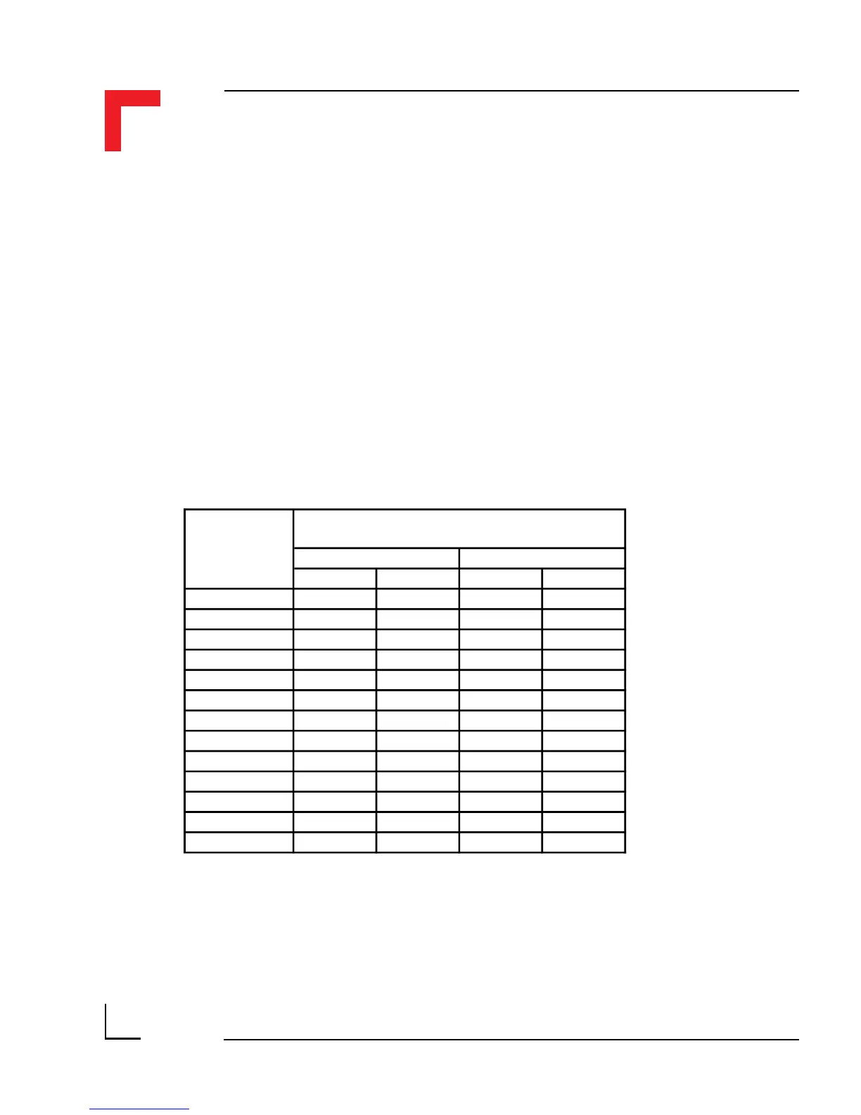
Table 5.2.5.2 shows the deviation from the required temperature for both
class A and class B PT100 sensors.
Table 5.2.5.2 Tolerances between Class A and Class B Sensors
Temperature
°C
Tolerance
Class A Class B
°C
Ω
°C
Ω
-200 ± 0.55 ± 0.24 ± 1.3 ± 0.56
-100 ± 0.35 ± 0.14 ± 0.8 ± 0.32
0 ± 0.15 ± 0.06 ± 0.3 ± 0.12
100 ± 0.35 ± 0.13 ± 0.8 ± 0.30
200 ± 0.55 ± 0.20 ± 1.3 ± 0.48
300 ± 0.75 ± 0.27 ± 1.8 ± 0.64
400 ± 0.95 ± 0.33 ± 2.3 ± 0.79
500 ± 1.15 ± 0.38 ± 2.8 ± 0.93
600 ± 1.35 ± 0.43 ± 3.3 ± 1.06
650 ± 1.45 ± 0.46 ± 3.6 ± 1.13
700 – – ± 3.8 ± 1.17
800 – – ± 4.3 ± 1.28
850 – – ± 4.6 ± 1.34
Driver software running under OS-9 supplies linearization data for use with
DIN standa