SMART I/O User’s Manual
©1996 PEP Modular Computers GmbHOctober 01, 1996 Page 6 - 27
6
Chapter 6 Communications Modules
6.2.10 Configuration
Jumper J1 - EEPROM Protection
6.2.11 Pinouts
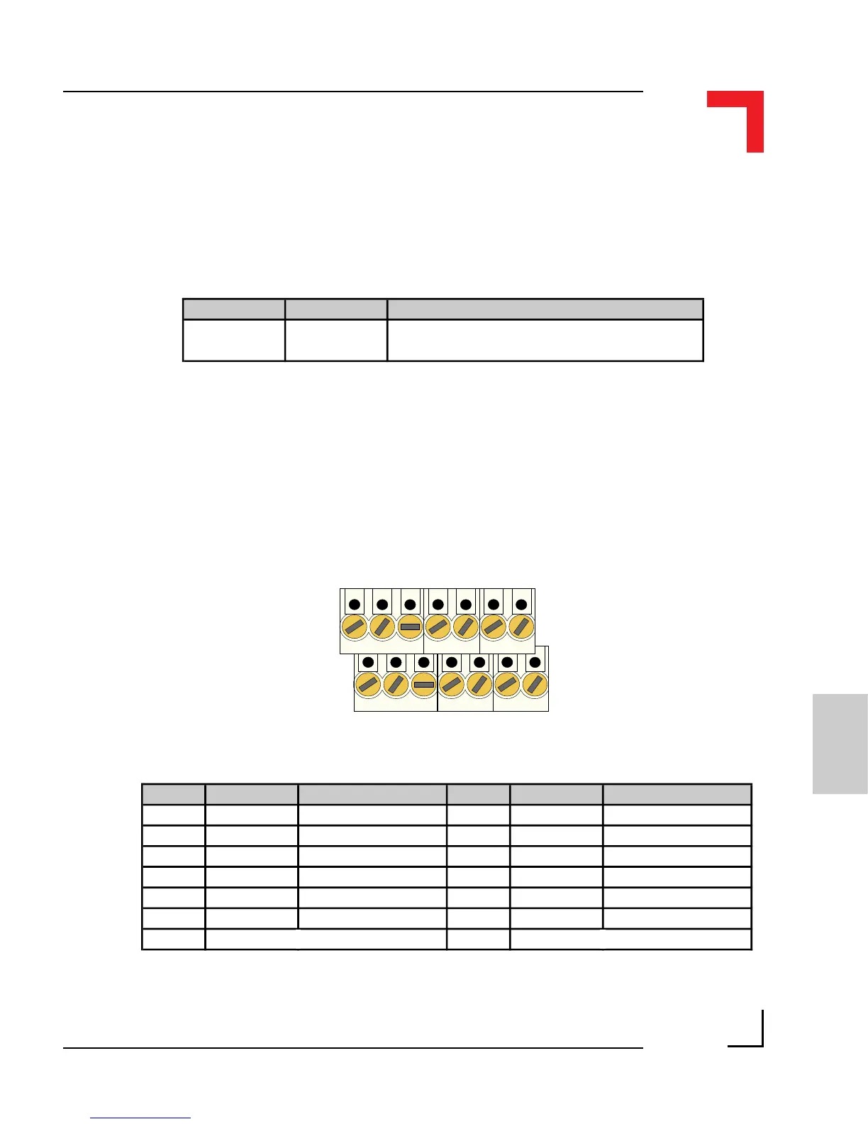
Screw Terminal Pinouts
The following shows the pinout/signal relationship for the SM-SSI when
connected to a particular screw terminal block.
Pin 1
Pin 2
Pin 13
Pin 14
Jumper Settings Description
J1
set EEPROM is not hardware write protected
open EEPROM is hardware write protected
Pin Nr. Signal Description Pin Nr. Signal Description
1 CLK+ SSI Clock + 2 CLOCK- SSI Clock -
3 DATA- SSI Data - 4 DATA+ SSI Data +
5 COM+ Common + 6 MATCH- Match -
7 RESET- Encoder Reset - 8 DIR- Direction -
9 EORC EOR Common 10 GND Ground
11 EOR1 End-of-Range 1 12 EOR2 End-of-Range 2
13
Reserved 14 Reserved