12
1, 6, 7, 27
26
1.2
1.1
I.
II.
x = 41
x = 41
x = 41
x = 36
x = 33
x = 17
6
6
6
6
1
1
SKYDECK Panel Slab Formwork
Instructions for Assembly and Use – Standard Configuration
A2 System components
Slab props
Dropheads SFK, Propheads SSK, SDFK
or Combiheads SCK fit on props with a
hole diameter of ø 38 – 40 mm.
With hole diameters > 40 mm, the
heads must be bolted diagonally using 2
Bolts ISO 4016 M12 x 40-4.6 galv., Mu,
item no. 035440. (Fig. A2.01)
Transition Heads SDSK (26) must al-
ways be bolted: see A9 Changing direc-
tion.
Prop loads over 33.3 kN:
bolting on of drophead for use with PEP
Slab Props using 2 Bolts DIN EN ISO
4016 M12 x 40-4.6 galv., Mu.
Preparing the Drophead
1. Push drophead wedge (1.1) and Drop-
head (1.2) upwards as far as possible.
(Fig. A2.06)
2. Insert drophead wedge.
3. Secure with hammer blow = shutter-
ing position.
Drophead SFK is ready for use.
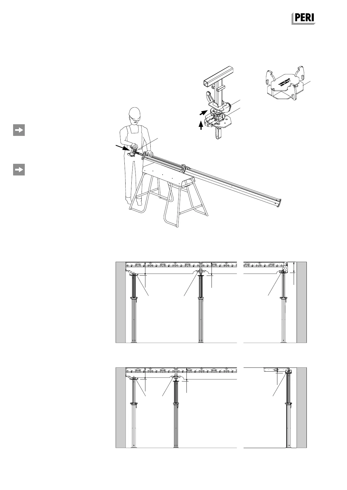
Preparing the slab props
1. Adjust the extension lengths of the
props. Clear room height minus
dimension x (Fig. A2.07). Take into
consideration the different overall
heights of the main beams: Main
Beam SLT 225 = 24 cm / Main Beam
SLT 150 = 19 cm.
2. Insert the prepared Drophead (1),
Prophead (6) or Combihead (7) into
the prop. The self-locking coupling is
secured automatically. (Fig. A2.01)
The prop is ready for use.
Fig. A2.06
Fig. A2.05
Fig. A2.07
Starting bay
Main Beam SLT 225
Starting bay
Main Beam SLT 150
End bay
Main Beam SLT 225
End bay
Panel SDP
SKYDEKC AuV_ex_791458.indb 12 13.12.16 16:54