40 . Frontier IR Single-range Spectrometers User's Guide
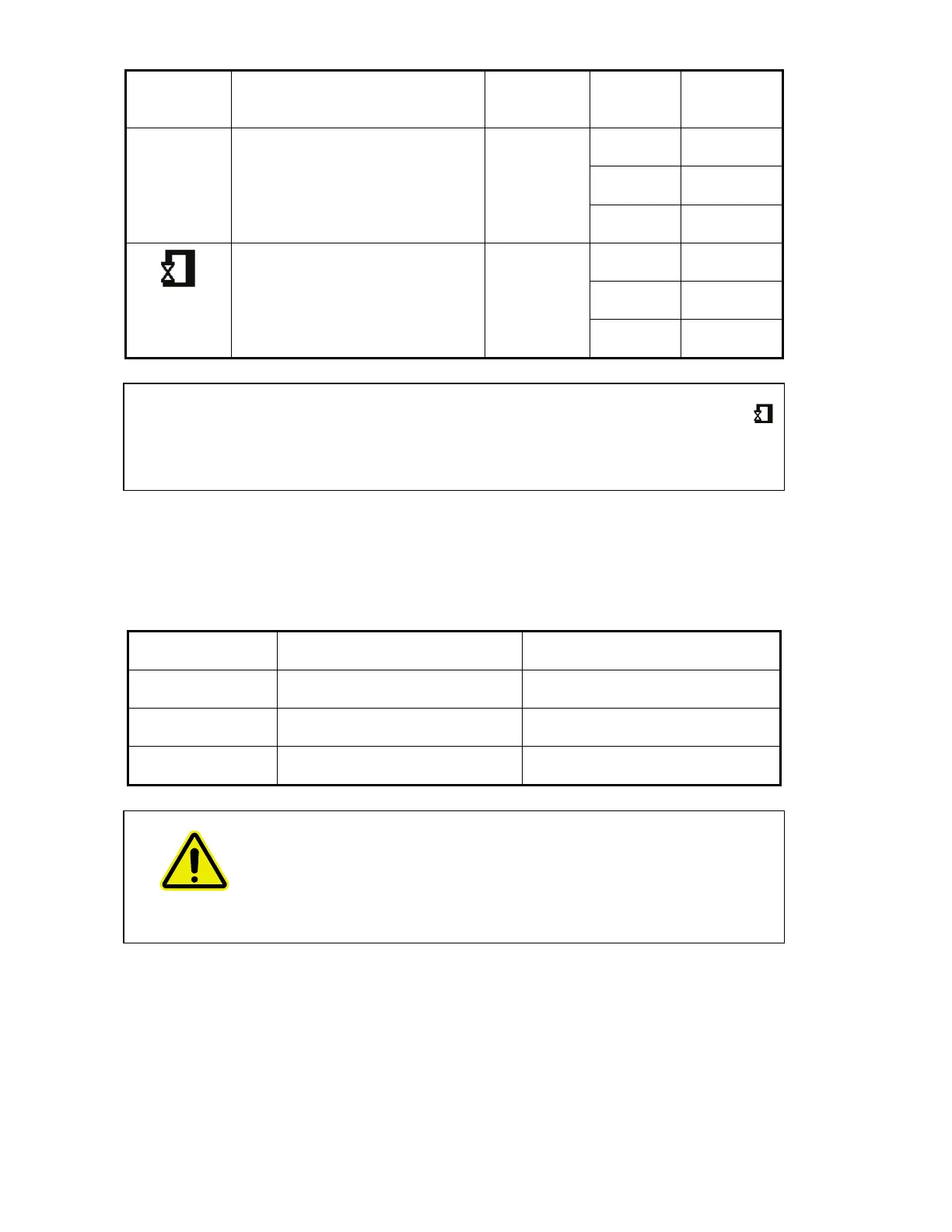
Icon Description Connector
Type
Voltages Maximum
Currents
EXT.R
Right external detector module.
Connects to an external detector
module. Usually the detector is
located in an accessory placed on
the right of the instrument.
15 way
high density
D-type
+12 V 0.65 A
−12 V 0.65 A
+5 V 4 A
Microscope external detector
module. Connects to a
PerkinElmer infrared microscope,
placed on the left of the
instrument.
15 way
high density
D-type
+12 V 0.65 A
−12 V 0.65 A
+5 V 4 A
CAUTION
Do not attempt to connect a monitor to either the EXT.R port or the
MICROSCOPE port or you will cause serious damage to the instrument
when it is switched on.
Connecting the spectrometer to the electrical supply
The power cable for the electrical supply plugs into the rear of the instrument. It has a
molded socket at one end. If it is necessary to fit a plug on the power cable, use the wire
color code below:
Plug Pin Wire Color (100–120 V) Wire Color (220–240 V)
Ground (Earth) Green or Green/Yellow Green/Yellow
Live Black Brown
Neutral White Blue
WARNING
To ensure safe and satisfactory operation of the instrument, it is
essential that the green or green/yellow ground (earth) wire of the
power cord is connected to a ground that complies with the regulations
of the local electricity supply authority (or equivalent body); ground
circuit continuity is essential for safe operation of the equipment.