PTO Clearances
The following visuals are provided to help or aid in determining PTO locations and clearances. For specific dimensions
please work through your local Peterbilt dealer. Multiple PTO’s are shown for layout purposes only. Power equipment,
i.e., drive shafts & power pumps are not included. Body builders should select the appropriate Chelsea or Muncie 24V electric over
air PTO’s for their application and customer requirements.
NOTE: All installations are only RH side PTO locations shown below are for reference only.
In order to ensure the PTO area remains clear of air equipment, electrical and emissions equipment, Peterbilt recommends
always ordering PTO controls, even when installing the PTO aftermarket. Contact your local dealer for assistance.
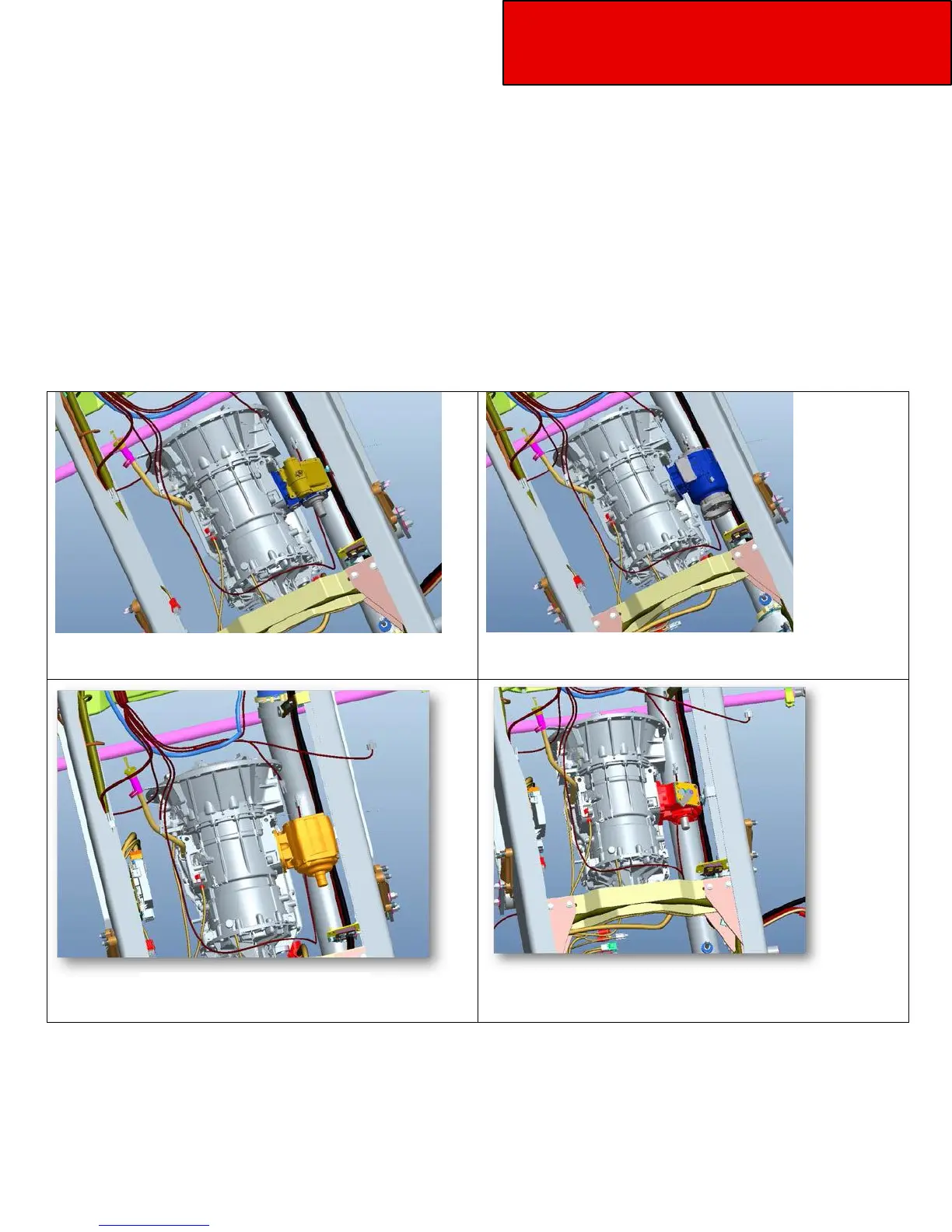
Below are shown example of PTO models installed on a 2000 Series Allison transmission:
Automatic Transmission – Allison 2000: