Appendix B
Weight Distribution
CALCULATIONS
Weight Distribution without Body
There are two primary equations used in weight distribution calculations:
• The first equation determines the portion of the load carried by the rear axle (Lr).
CGf
Lr =
WB
X L Portion of Load Carried by the Rear Axle Equation 1
• The second determines the portion of the load carried by the front axle (Lf).
Lf = L - Lr Portion of Load Carried by the Front Axle Equation 2
Note:
For the purposes of calculation, the load (L) in these equations can be either actual revenue
producing load or it can be other weight that is carried such as the van body or an optional fuel
tank.
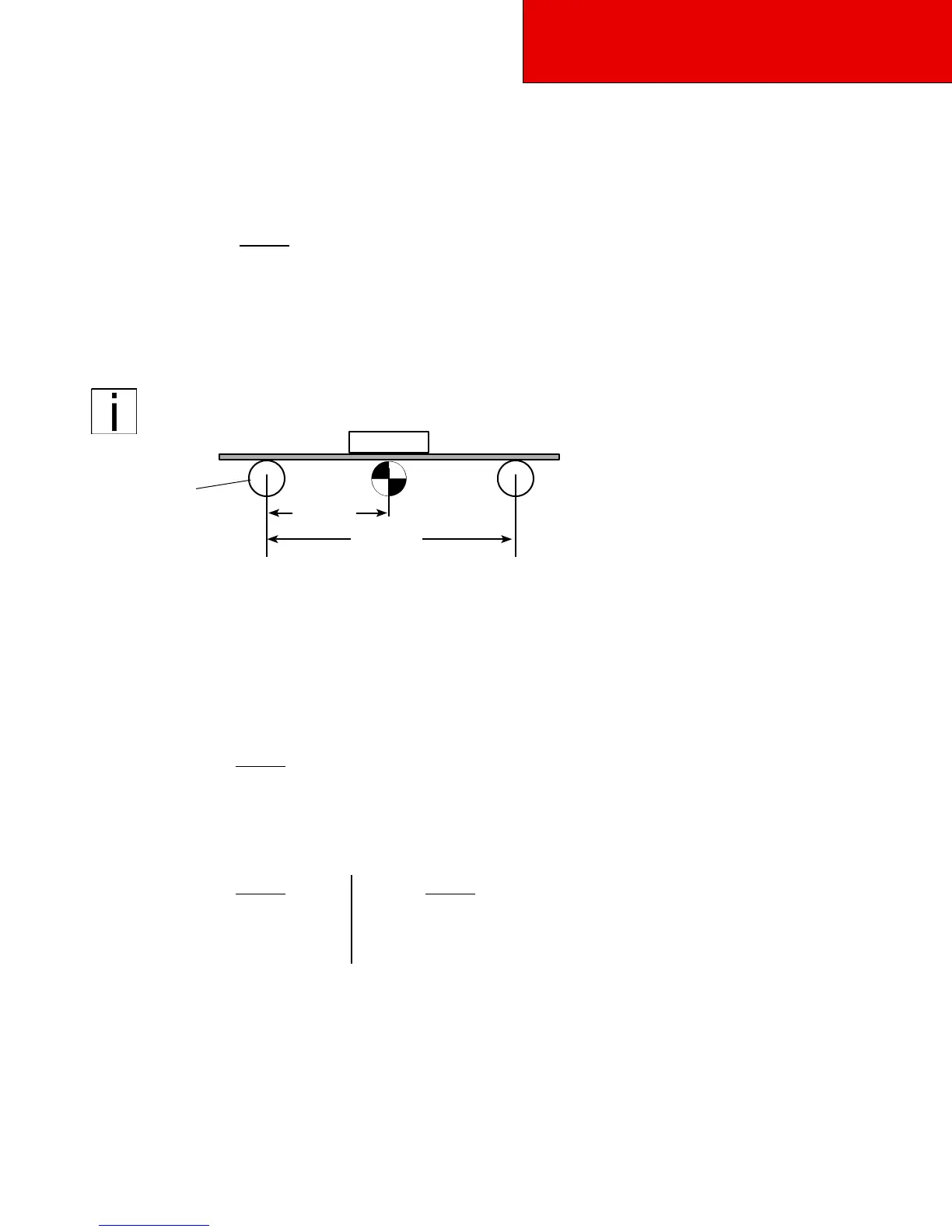
Front Axle
Figure B-1. Balanced Load: CGf 100 in. from front axle
Step 1.
Figures B–1 and B–2 show a representation of a 214 inch (5435.6 mm) wheelbase (WB) truck de-
signed to carry a 100–lb. (45.3–kg) load. Figure B–1 represents a truck with the load placed an equal distance
between the two axles.
a.
For our balanced load example we need to establish the center of gravity location (CGf, as
shown in Figure B–1) by dividing the wheelbase by 2:
214
CGf =
2
= 107 in (2717.8 mm)
b.
Use equations 1 and 2 to determine the portions of the load carried by each axle.
•
The weight distribution is calculated as illustrated below:
Lr =
CGf
WB
X L
107
214
(100) = 50 lbs (23 kg)
Lf = L - Lr 100 - 50 = 50 lbs (23 kg)
•
Since the load is centered between both axles, 50 percent of the load is carried by each
axle: i.e., 50 lb. (22.6 kg) is distributed to each axle.