Section 5
Frame Layouts and Body
Mounting
FRAME LAYOUTS
The dimensions in the frame layout section are intended to aid in layout of the chassis, and to help determine the best
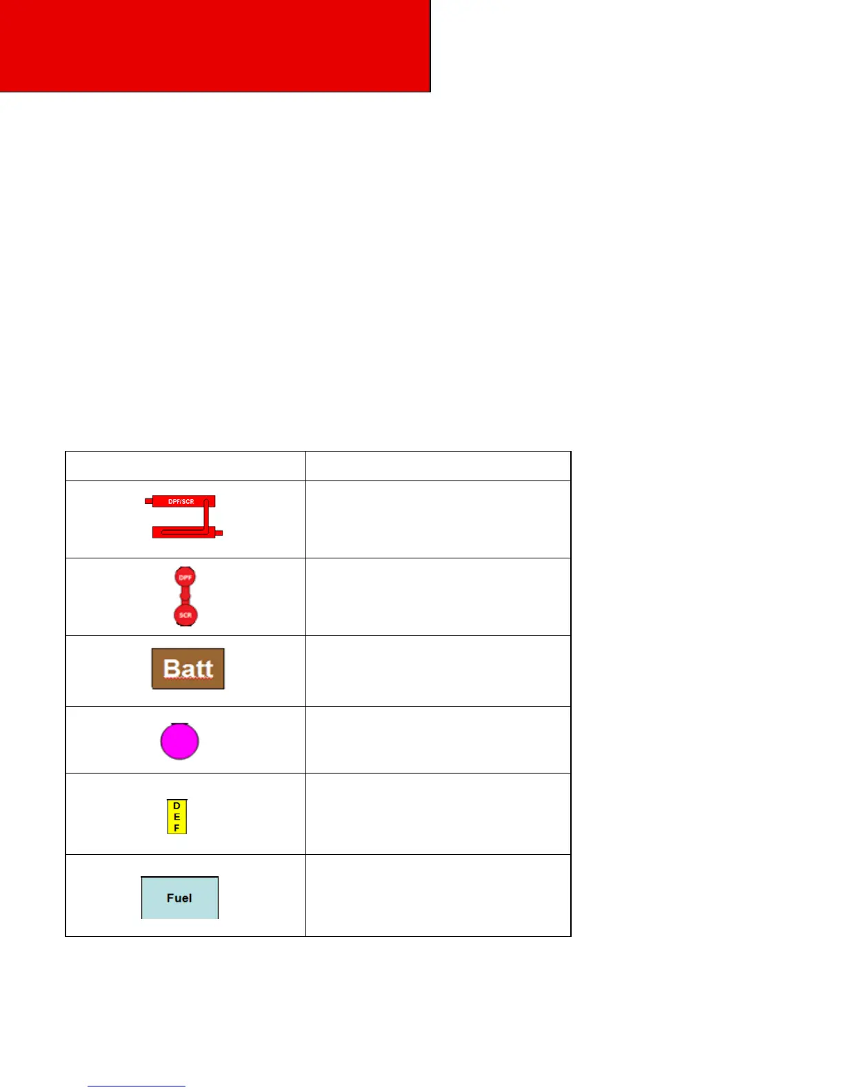
possible combination of fuel tanks, battery boxes. The diesel particulate filter (DPF), SCR canister, and Diesel Exhaust
Fluid (DEF) tank. For your application, the layouts focus on the under cab area, with appropriate dimensional
information in- cluded for pertinent back of cab components. Not all optional equipment is included in this section;
additional components may be placed on the rail behind components shown. The Back of Cab components are shown
primarily for reference. For more specific requirements, work with your local Peterbilt Dealer. Please read the
instructions carefully. The following dimensions are consistent across the entire section to aid in the comparison of one
layout option versus another.
The visual index that follows will give you a quick overview of the layout that is included.
Visual Index
Table 5-1 Symbols