Section 5
Frame Layouts and Body
Mounting
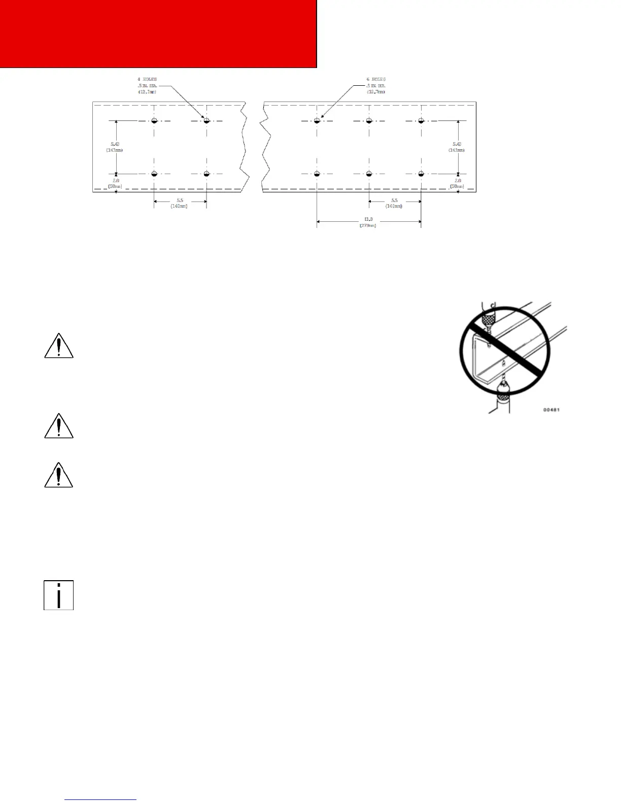
Figure 5-8 Crossmember-Gusset Hole Pattern Requirements. [inch(mm)]
Frame Drilling
WARNING: When mounting a body to the chassis, DO NOT drill holes in the
upper or lower flange of the frame rail. If the frame rail flanges
are modified or damaged, the rail could fail prematurely and
cause an accident. Mount the body using body mounting brack-
ets or U–bolts.
WARNING:
Use care when drilling the frame web so the wires and air lines routed inside the rail
are not damaged, Failure to do so could cause an inoperable electrical or air sys-
tem circuit.
WARNING:
Do not drill new holes any closer than 2 inches (50 mm) to existing holes. Frame
drilling affects the strength of the rails.
Hole Location Guidelines
Holes must be located from the flange as indicated in Figure 5-7. They must be no closer than 2 inches (50 mm) to
each other.
Note:
If your design permits placement of body mounting brackets at crossmember locations, you
can use the crossmember gusset bolt holes for body mounting. See Figure 5-8
BODY MOUNTING USING U–BOLTS
Spacers
If the body is mounted to the frame with U–bolts, use a hardwood sill [minimum 1/2 inch (12 mm) thick]
between the frame rail and body frame to protect the top surface of the rail flange.