Section 5
Frame Layouts and
Body
Mounting
Body Subframe
(Rail)
Chassis Frame
(Rail) Sill
Spacer
Brackets
Figure 5-4 Spacer Between Frame Sill and Body Rail - Rubber or Plastic
When mounting a body to the chassis with brackets, we recommend designs that offer limited amount of relative move-
ment, bolted securely but not too rigid. Brackets should allow for slight movement between the body and the chassis.
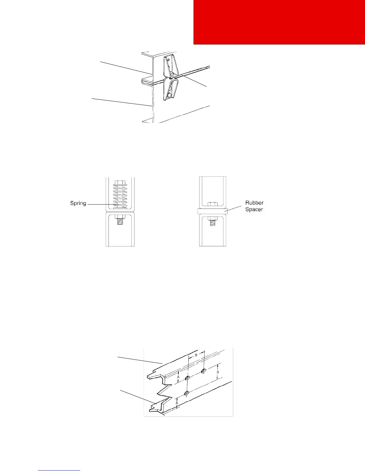
For instance, Figure 5–5 shows a high compression spring between the bolt and the bracket.
Figure 5-5 High Compression Spring Between the
Mounting Bolt and Upper Bracket
Figure 5-6 Rubber Spacer Between Brackets
Another possibility is mounting a rubber spacer between the brackets. See Figure 5-6.
These designs will allow relative movement between the body and the chassis during extreme frame racking situations.
Extreme frame racking and mountings that are too rigid, could cause damage to the body. This is particularly true with
tanker installations.
Mounting Holes
When installing the lower bracket on frame rails the mounting holes in the chassis frame bracket and frame rail must comply
with the general spacing and location guidelines illustrated in Figure 5-7. The hole diameter should not exceed the bolt diam-
eter by more than .060 inches (1.5 mm).
Upper
Frame
Flange
Lower Frame
Flange
A A or B Equal to or
Greater Than 2 Inches
(50 mm)
Figure 5-7 Hole Locations Guidelines for Frame Rail and Bracket