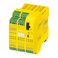
PSR-TRISAFE-S
A-4
PHOENIX CONTACT 103503_en_03
Inserting signal inputs and outputs in the connection editor
4-11
Intended use ....................................................... 1-7, 3-9
L
LEDs for inputs and outputs ....................................... 3-6
Low Voltage Directive 2006/95/EC............................. 1-5
M
Machinery Directive 2006/42/EC......................... 1-5, 2-4
Machinery Directive 98/38/EC.................................... 1-5
Method of operation of the PSR-TRISAFE-S system . 2-1
MINI-SYS-PS system power supply unit .................. 3-16
MINI-SYS-PS, system power supply unit ................. 3-16
ModeSelector (safe functional block)......................... 4-7
MutingPar (safe functional block) ............................... 4-8
MutingPar_2Sensor (safe functional block)......... 2-6, 4-8
MutingSeq (safe functional block) .............................. 4-8
O
Online help................................................................. 6-1
Call ......................................................... 1-8, 4-2, 4-9
Online tool tips in the connection editor.................... 2-12
Outputs O0 - O3........................................... 3-1, 3-7, 3-8
P
Parameterization editor ............................................ 4-15
Parameterizing inputs and outputs.................... 4-15, 5-1
Password protection ......................................... 2-13, 5-9
Performance level PLe according to DIN EN ISO 13849..
3-8
Personnel, requirements ............................................ 1-1
Power supply for sensors and control devices ........... 3-9
Printing parameters.................................................. 4-17
Problems and solutions.............................................. 7-1
Project configuration and startup, overview................ 5-1
Project documentation ...................................... 4-19, 5-3
Project password, see Password protection
Project Wizard.......................................................... 4-10
PSR-TBUS DIN rail connector ................. 3-4, 3-14, 3-16
Module communication ........................................ 2-3
PSR-TRISAFE-S........................................................ 2-5
"Confirm" button ................................................... 3-6
Alarm outputs M0 - M3 ......................................... 3-9
Behavior with no IFS-CONFSTICK.............. 3-12, 5-8
Clock outputs T0, T1 ..................................... 2-8, 3-9
Connecting the signal lines................................. 3-17
Connecting the supply voltage ........................... 3-16
Connection terminal blocks .................................. 3-1
Cross-circuit detection ......................................... 2-8
Diagnostic and status indicators........................... 3-4
Diagnostic tools.................................................... 2-9
Downloading the configuration using the IFS-
CONFSTICK ........................................................ 5-7
Ground switching outputs O0-, O1-.................... 3-10
Hardware description ........................................... 3-1
I/O device error detection ..................................... 2-8
IFS-CONFSTICK, see IFS-CONFSTICK
Installation .......................................................... 3-13
LEDs for inputs and outputs ................................. 3-6
Operating and indication elements....................... 3-4
Password protection........................................... 2-13
Possible operating status ..................................... 3-3
Safe outputs O0 - O3............................................ 3-8
Safety functions, possible..................................... 2-4
Signal inputs......................................................... 3-7
Status indicators................................................. 2-12
Supply outputs A1, A2.......................................... 3-9
Supply voltage via the MINI-SYS-PSI system power
supply unit .......................................................... 3-16
System overview .................................................. 2-1
Uploading the project ........................................... 5-9
USB interface ..................................................... 3-11
Using the system.................................................. 2-4
PSR-TRISAFE-S confirm button 2-5, 3-4, 3-6, 5-2, 5-6, 5-7
PSR-TRISAFE-S connection terminal blocks.... 3-1, 3-17
PSR-TRISAFE-S diagnostic and status indicators..... 3-4
PSR-TRISAFE-S inputs ............................................. 3-7
PSR-TRISAFE-S installation.................................... 3-13
PSR-TRISAFE-S mounting ...................................... 3-13
PSR-TRISAFE-S operating and indication elements . 3-4
PSR-TRISAFE-S operating status ............................. 3-3
PSR-TRISAFE-S removal ........................................ 3-15
PSR-TRISAFE-S signal inputs................................... 3-7
PSR-TRISAFE-S status indicators.................... 2-12, 3-4
PSR-TRISAFE-S supply voltage .............................. 3-16
PSR-TRISAFE-S system description ......................... 2-1

 Loading...