5.8
Section 5
Maintenance
Pinnacle Operators Manual
Pickering Laboratories Inc.
Ambient Reactor Replacement
The Ambient Reactor is Item 13 (on dual systems only).
1. Shutdown the post-column system and let the reactor cool for at
least 30 min.
2. Disconnect the two fingertight fittings at either end of the ambient reactor. These will be located on the
manifold (Item 6) and the inlet of the detector.
3. Loosen the screw that holds the black spindle to the fluidics panel with a 3/32" Alan wrench.
4. Remove the spindle and remove the used reactor.
5. Slide the new reactor onto the spindle and fasten to the fluidics panel.
6. Re-connect the fingertight fittings to the manifold and the union (Items 6 and 14). Do not overtighten the
fittings.
7. Start the LC pump and inspect for leaks.
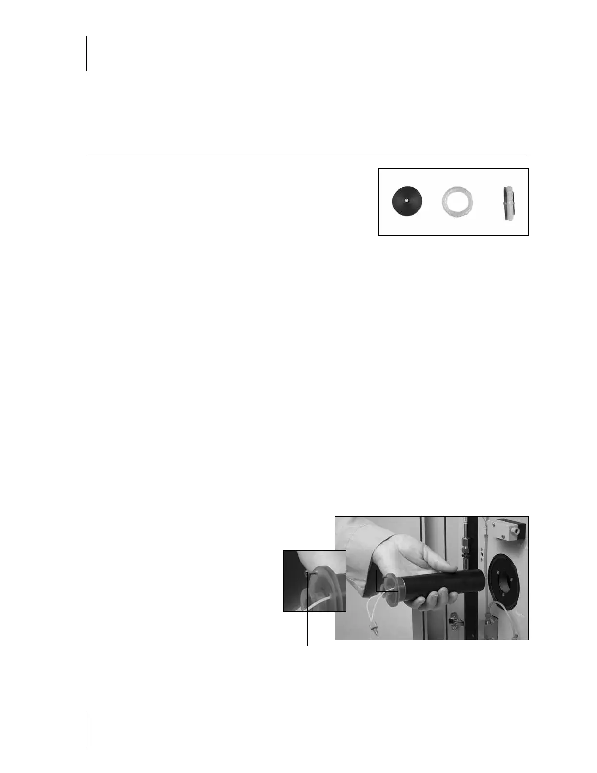
Replacement of Heated Reactor Cartridge
The Heated Reactor is Item 7. Please refer to Figure 5-4 for removal of the Reactor Cartridge.
1. Shutdown the post-column system and let the reactor cool until it is a safe temperature for handling (below
30˚C).
2. Disconnect the fingertight fittings connected to the heated reactor. These will be located on the manifolds
(Items 6 and 8) for duplex systems or on the manifold and union in simplex systems (Items 8 and 14).
3. Loosen the retaining screw at the top of the reactor cartridge using a flathead screwdriver
(see Figure 5-4).
4. Gently slide the Reactor Cartridge out of the reactor
housing.
5. Replace the heated reactor cartridge with the proper
volume (see Appendix).
6. Reconnect the two fingertight fittings.
Do not overtighten. The inlet tubing of the
heated reactor is marked with a piece of
black shrink tube and connects to mixing
manifold I (Item 8).
Start the LC pump and inspect for leaks.
Figure 5-4
Retaining Screw
Figure 5-3