10 PARTS REPLACEMENT & REPAIR
Technical manual Planmeca ProX 51
10.5 Replacing Generator PCB
1. Disconnect the X-ray unit from the mains or switch off the power supply.
2. Remove the generator housing. Refer to section 10.1 “Removing generator housing” on
page 45.
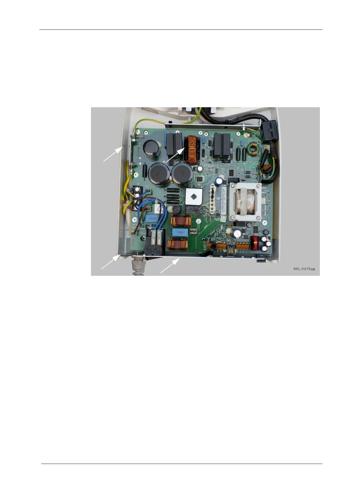
3. Measure that the mains voltage is not present at the mains input terminals (P5) marked N
and L (see figure below).
4. Disconnect the connectors from terminals P1, P3, P5, P6 P7, P8 and P9.
5. Loosen the four M4x8 ISO 7380 screws of the generator assembly frame (white arrows in
the figure). Lift the generator assembly upwards. The generator assembly can now be
lifted away from the wall adapter.
6. Remove the ten M4x8 DIN 912 attachment nuts and ø4.3 DIN 6798 washers from the
Generator PCB. Lift the generator assembly away from the wall adapter and open the two
M3x6 DIN 912 screws located behind the generator assembly frame.
 Loading...


