10 PARTS REPLACEMENT & REPAIR
58 Planmeca ProX Technical manual
3. Remove the following covers: generator housing, tube head covers, tube head support
cover and bracket arm covers. Remove the control panel from the generator assembly.
Refer to the appropriate sections.
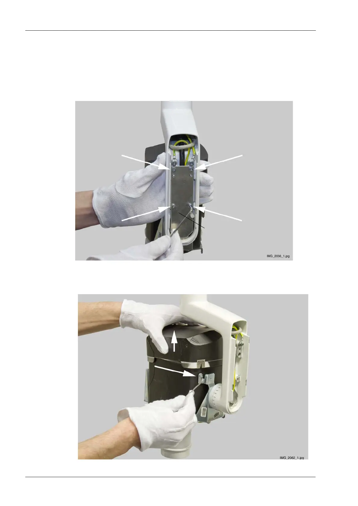
4. Unscrew four baffle plate attachment screws using a 3 mm Allen key (white arrows). Note,
that the white reset button and the two cover attachment screws will drop away from its
position when you remove the plate. The reset button and the attachment screws must be
replaced to the same position when attaching the plate back to its position.
5. Unscrew the attachment screw of the protective lead using a 2.5 mm Allen key and
remove the lead.