7.39
FINAL DRIVE
7
Hub Installation
1. Start the wheel bearing carrier onto the drive shaft.
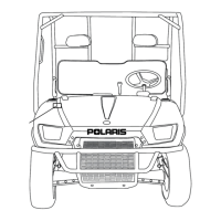
2. Align the bottom of carrier housing and lower control arm.
Slide the lower control arm bushings into place. Secure
with the lower control arm bolt.
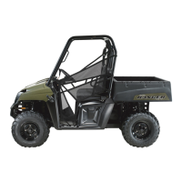
3. With the drive shaft placed in the wheel bearing carrier,
align the carrier with the top control arm. Secure with the
upper control arm bolt.
NOTE: The lower shock bolt may need to be
removed to allow the upper A-arm to move more
freely.
4. Torque the top and bottom A-arm bolts as shown in the
photo.
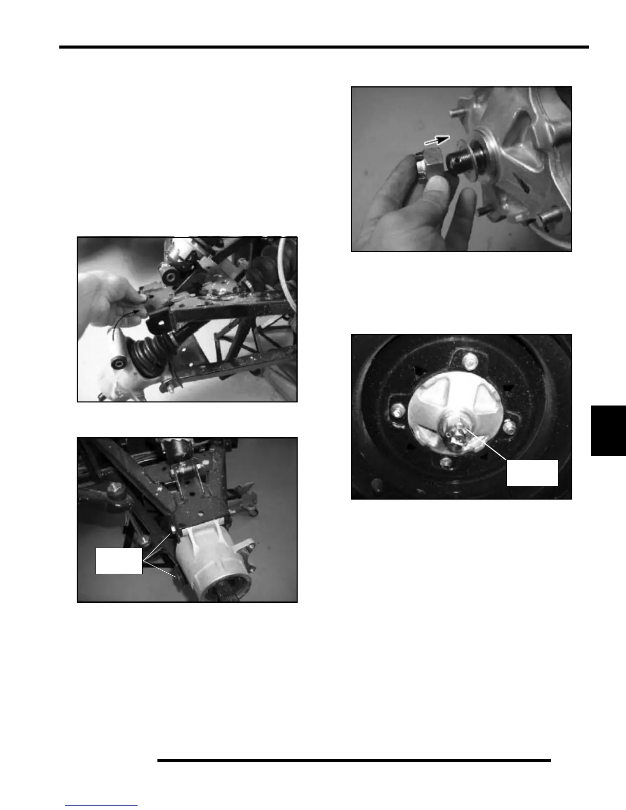
5. Install the hub assembly onto the rear drive axle.
6. Install the washer with domed side out. Install the spindle
retainer nut.
7. Install the wheel, washers, and wheel nuts. Torque wheel
nuts to specification. See “Torque Specifications” table on
page 7.3.
8. Lower the vehicle. Torque the spindle retaining nut to 110
ft.lbs. (149 Nm). Install a new cotter key and the hub cap.
30 ft. lbs.
(41 Nm)
110 ft. lbs
(149 Nm)
 Loading...