EasyManuals Logo

Poly G7500 Administrator's Guide

Poly G7500
156 pages
To Next Page IconTo Next Page
To Previous Page IconTo Previous Page
Page #44 background imageLoading...
Page #44 background image
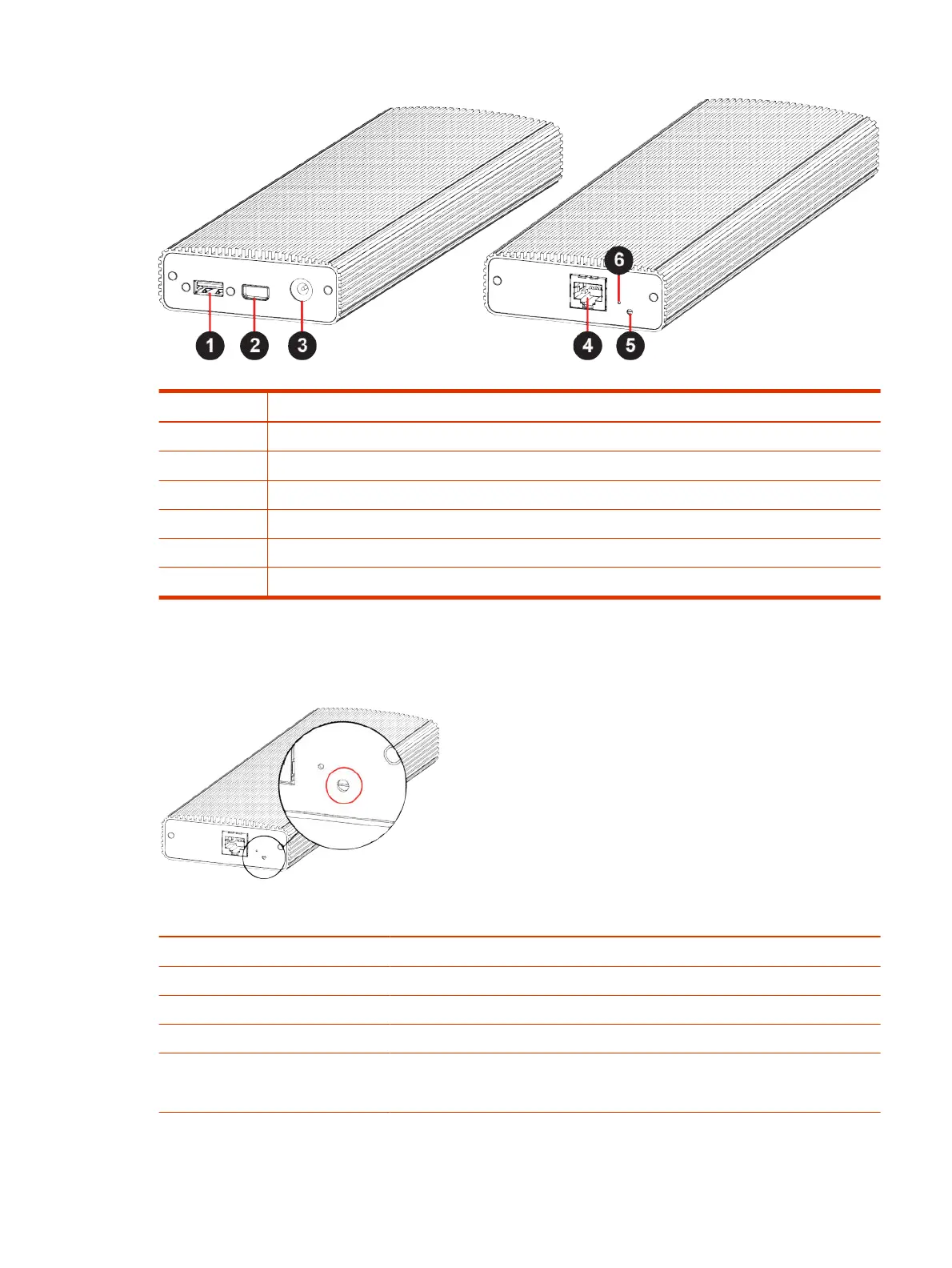
Table 3-5 Microphone Adapter Port Descriptions
Ref. Number Port Description
1 USB 2.0 debugging port
2 Polycom microphone Walta-Walta connector
3 Power
4 Link-local network (LLN) connection
5 LED status indicator
6 Factory restore pinhole
LED Status Indicators for the Microphone Adapter
Use the LED to get information on the state of your microphone adapter.
Table 3-6
Microphone Adapter LED Status Indicators
Indicator Status
Blinking white Powering on
Solid white On
Blinking blue Ready to pair
Solid blue Paired successfully
Blinking green and blue Update in progress
Factory restore in progress
LED Status Indicators for the Microphone Adapter 33

Table of Contents

Other manuals for Poly G7500

Questions and Answers:

Question and Answer IconNeed help?

Do you have a question about the Poly G7500 and is the answer not in the manual?

Poly G7500 Specifications

General IconGeneral
NetworkGigabit Ethernet
BluetoothBluetooth 5.0
InteroperabilitySIP, H.323
Audio FeaturesNoiseBlockAI, Acoustic Fence
CameraSupports EagleEye cameras
ConnectivityHDMI, USB, Ethernet
Video Standards and ProtocolsH.264 AVC, H.265
Video Input1 x HDMI
Video Output2 x HDMI
Audio StandardsG.711, G.722, G.719
Audio Input3.5 mm line-in
Audio Output3.5 mm line-out, HDMI
WirelessWi-Fi 802.11ac
SecurityAES-128
Daisy ChainSupported with microphone arrays
Power SourceAC power
Video ResolutionUp to 4K Ultra HD (3840 x 2160) at 30 fps

Related product manuals