105
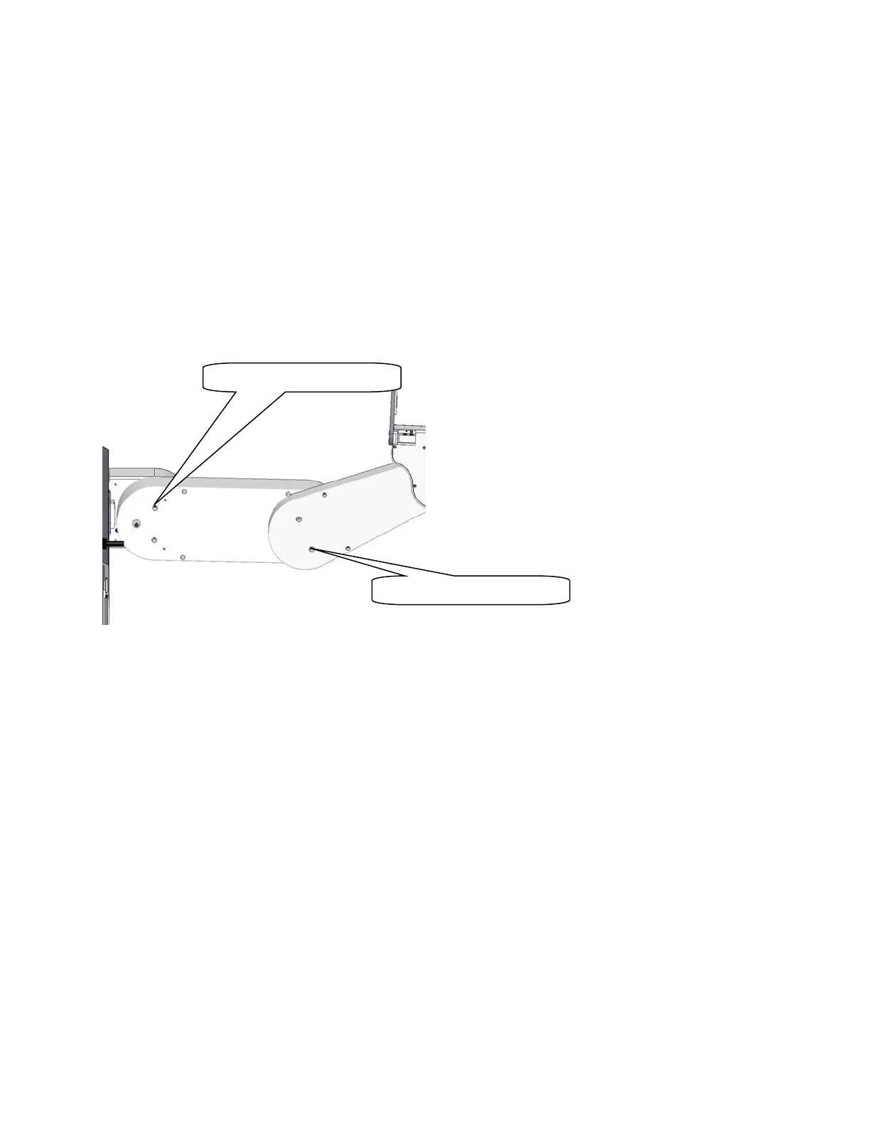
1. Loosen the 2 Motor Locking Screws on the bottom of the Inner Link. One screw requires a 2.5mm
driver and the second requires a 3.0mm driver.
2. Tighten the 2 screws again. The J3 belt is automatically re-tensioned.
3. The above procedure is an approximate procedure. Its accuracy is limited by the fact that the J3
belt tension will vary according the orientation of the J3 output pulley. The timing belts are very
stiff. A .002 in eccentricity (which is the specified tolerance) in the output pulley can cause a 50%
variation in the belt tension, depending on the orientation of the output pulley. If performing the
quick tensions adjustment outlined in steps 1 and 2 above does not resolve a J3 instability (loud
buzzing noise), it may be necessary to remove the controller and J3 belt cover to gain access to
the J3 belt, and then set the belt tension by using a belt tension meter as described in Appendix
E, while checking for the minimum belt tension every 10 degrees of rotation of the J3 output
pulley. This more extensive procedure should be required only rarely.
Tensioning the J4 Belt (Before 2014)
Tools Required:
1. Gates Sonic Belt Tension Meter, Model 507C
2. 3.0mm hex driver or hex L wrench
3. 2.5mm hex driver or hex L wrench
Prior to 2014 the J4 belt had the tensioning procedure described below. Starting with 2014 shipments, an
access hatch was added to the bottom of both the inner link and outer link to make J3 and J4 belt access
easy and belt tensioning more accurate.
To tension the J4 Belt the user must:
1. Remove the outer link cover.
2. Remove the gripper controller PCA.
3. On robot sold before January 2012, remove the Slip Ring Clamp and remove the 4 M3 X 10
FHCS screws retaining the J4 belt cover. Tip the belt cover upwards to access the timing belt.
4. Loosen the M4 SHCS and M4 Shoulder Motor Locking Screws on the bottom of the Outer Link
Motor Lockin
Screws
Motor Lockin
Screws