PreciseFlex_Robot
68
Each of these interfaces is described in detail in the following sections. In addition, the robot's controller,
which is mounted in the inner link of the robot, may contain additional interfaces (e.g. inputs or outputs).
Please refer to the Guidance 1000A/B Controllers, Hardware Introduction and Reference Manual for
additional information.
DANGER: The Guidance 1400B controller, and the 24 VDC and 48 VDC
power supplies are all open frame electrical devices that contain
unshielded high voltage pins, components and surfaces. . The main AC
power should always be disconnected before the Facilities Panel is
removed.
If the pneumatic gripper option is ordered one air line is routed through the interior of the robot. At the
Facilities Panel, this air line is presented in a fitting on a sub plate mounted to the facilities panel. The
other end of this line exits at the Outer Link. When using this line, clean, dry external air should be
provided.
CAUTION: The maximum air pressure that can be conveyed by the air
lines through the robot is 75 PSI.
pplying a pressure exceeding this level
may disconnect interior connections or damage fittings or hoses. If a
hi
her pressure is required, an external air line should be utilized.
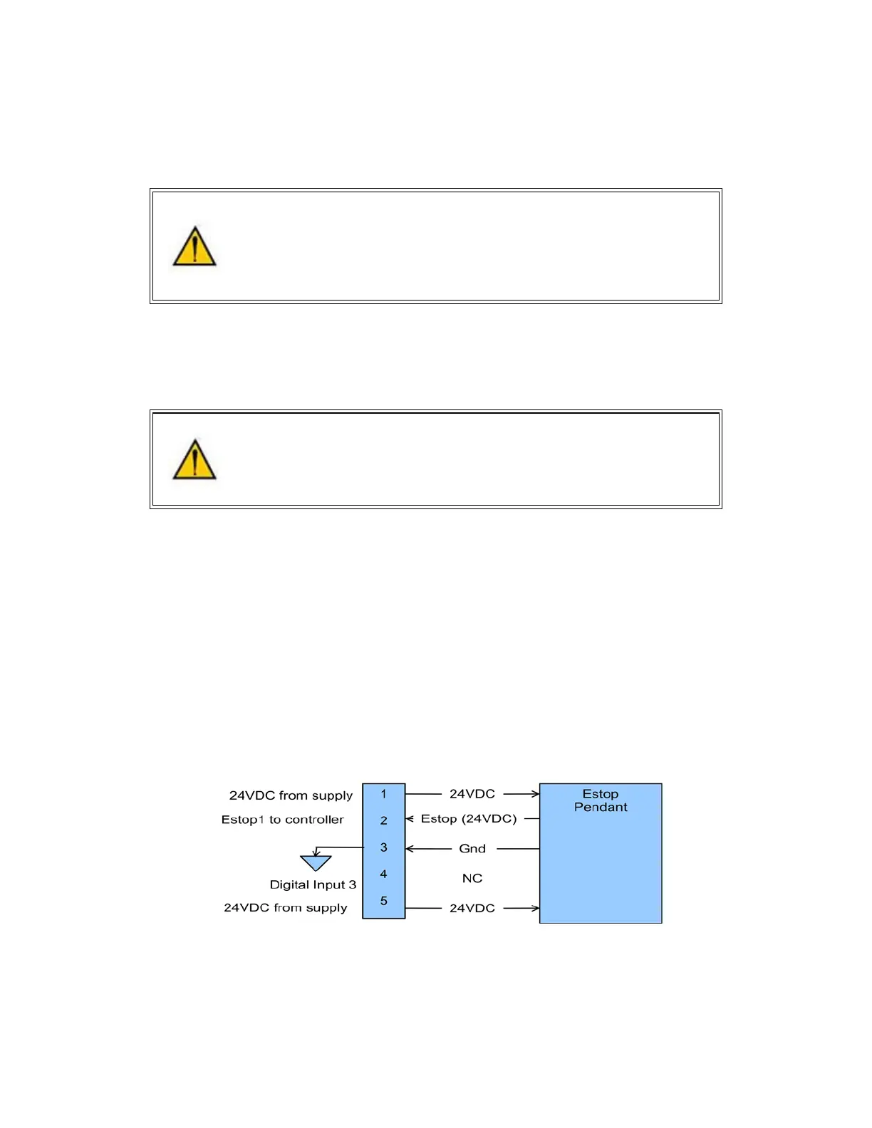
E-Stop Connector
The standard E-Stop connector is the green Phoenix connector on the Facilities Panel. Note the E-Stop
pins on the MCP Interface (below) are in series with the E-Stop signals on the Phoenix E-Stop connector.
An E-Stop box or circuit can be plugged into either one of these two connectors. However in order for the
robot to allow motor power to be enabled the E-Stop circuit must connect 24 VDC to E-Stop1 in both of
these two connectors. If no E-Stop box or circuit is connected, then the circuit must be completed with a
jumper from pin 1 to pin 2 on the Phoenix connector or from pin 1 to pin 6 on the MCP connector. The
robot is shipped with a Phoenix jumper plug PN 1851070 and a jumper plug in the 9 pin Dsub connector
that satisfy these requirements. Unlike the Digital IO circuits, the E-Stop circuit cannot be configured as
“Sourcing” or “Sinking”. If a remote signal (for example from a PLC) is used to trigger E-Stop, it should be
wired to a relay that closes the circuit between pins 1 and 2. When the robot is mounted on a Linear Axis,
the MCP Interface is extended to the end cap of the Linear Axis.