Introduction to the Hardware
7
DANGER: In addition to exposed high voltage pins and components, the
heat sinks on the Power Supplies are not grounded and expose high
voltage levels. AC power to the robot must be disconnected prior to
accessin
these units.
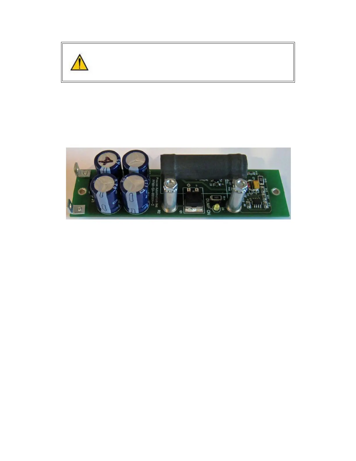
Energy Dump Circuit
The 48 VDC supply has a regulated output and an overvoltage protection circuit that is triggered if the
voltage reaches 60 volts. Rapid deceleration of the robot motors can generate a Back EMF voltage that
can pump up the motor voltage bus. In order to avoid bus pump up, an Energy Dump Circuit is
connected to the 48 VDC bus.
Remote Front Panel, E-Stop Box and Manual Control Pendant
For users that wish to have a hardware E-Stop button, Precise offers an E-Stop Box or a portable
Hardware Manual Control Pendant that includes an E-Stop button. The E-Stop box can be plugged into
the green Phoenix connector in the connector panel in the base of the robot. The E-Stop box completes
a circuit from the top pin, Pin 1 (24VDC) to Pin 2 (E-Stop) in this connector. If this circuit is not completed
it is not possible to enable motor power to the robot. If no E-Stop box or Manual Control Pendant is
connected, a jumper must be connected between these two pins to enable robot motor power. For those
applications where an operator must be inside the working volume of the robot while teaching, a second
teach pendant with a 3-position run hold switch is available. The Manual Control Pendants can be
plugged directly into the 9 pin Dsub connector mounted on the robot's Facilities Panel in the base of the
robot. The E-Stop connections are also present on the 9 pin Dsub connector and each of these units
provides the hardware signals to permit power to be enabled and disabled.