Hardware Reference
73
The RS485 Remote IO Module (GIO) provides 12 general purpose optically isolated digital input signals
and 8 general purpose optically isolated digital output signals. Two inputs, 11 and 12, can be optionally
configured as analog inputs by means of jumpers J1 and J2. Connecting J1 to pins 1 and 2 (default)
configures these inputs as digital and connecting pins 2 and 3 configures them as analog (if the analog
option has been ordered). These input and output signals are intended for interfacing to tooling and
sensors or for general application needs. This board is connected to the controller by an RS485 serial line
that allows the controller to scan the GIO I/O with a nominal period of 4 milliseconds.
The DIO signals are accessible via the DB25 female connector that is mounted on the facilities panel
when this option is ordered. The DIO signals addresses are determined by a base address set by a DIP
switch on the DIO board. For the PF400 robot without the linear axis option the DIO option is located at
the robot connector panel and for both this location and also for the location at the end of the optional
linear axis, all the address jumpers will NOT be installed, which sets the address of this module to “8”.
This address avoids conflicts with other RS485 network controllers for the gripper and optional linear axis.
See “Installing the optional G IO Board” under Service Procedures for details on installing this module.
PF3400 3kg IO in Base of Robot (GIO)
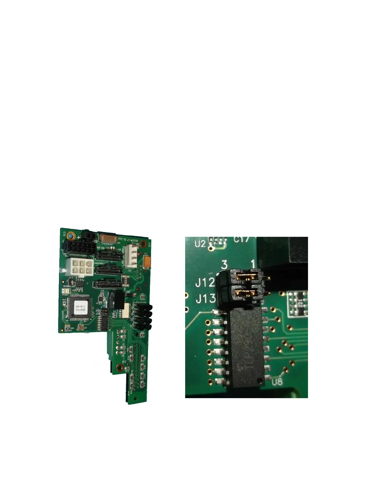
For the 3kg PF400, the GIO function is integrated as a standard feature in the base of the robot, however
only inputs 1-8 are supported. All outputs are sourcing and cannot be changed. Inputs are set to sinking
in the factory and can be changed in blocks of 4 by moving J12 and J13 to connect pins 1 and 2, instead
of 2 and 3.