135
The J1 Motor Assembly is comprised of the J1 motor, connectors, and a timing belt pulley.
The user must:
1. Remove AC power and connectors from the base of the robot.
2. Unfasten the robot from its mounting surface by removing 4 M6 SHCS.
3. Lay the robot on its back, being careful the robot links do not fall over and damage the paint. It is
a good idea to wrap the links with a protective cover first, such as a sheet of foam.
4. Remove the top cover by removing 4 M5 Low Head Cap Screws.
5. Remove the Front Cover by sliding it out.
6. Remove the left splash guard by removing the M3X8 SHCS and M3 star washer.
7. Remove the screws attaching the Electronics Chassis and ground lug to the Bottom Mounting
Plate.
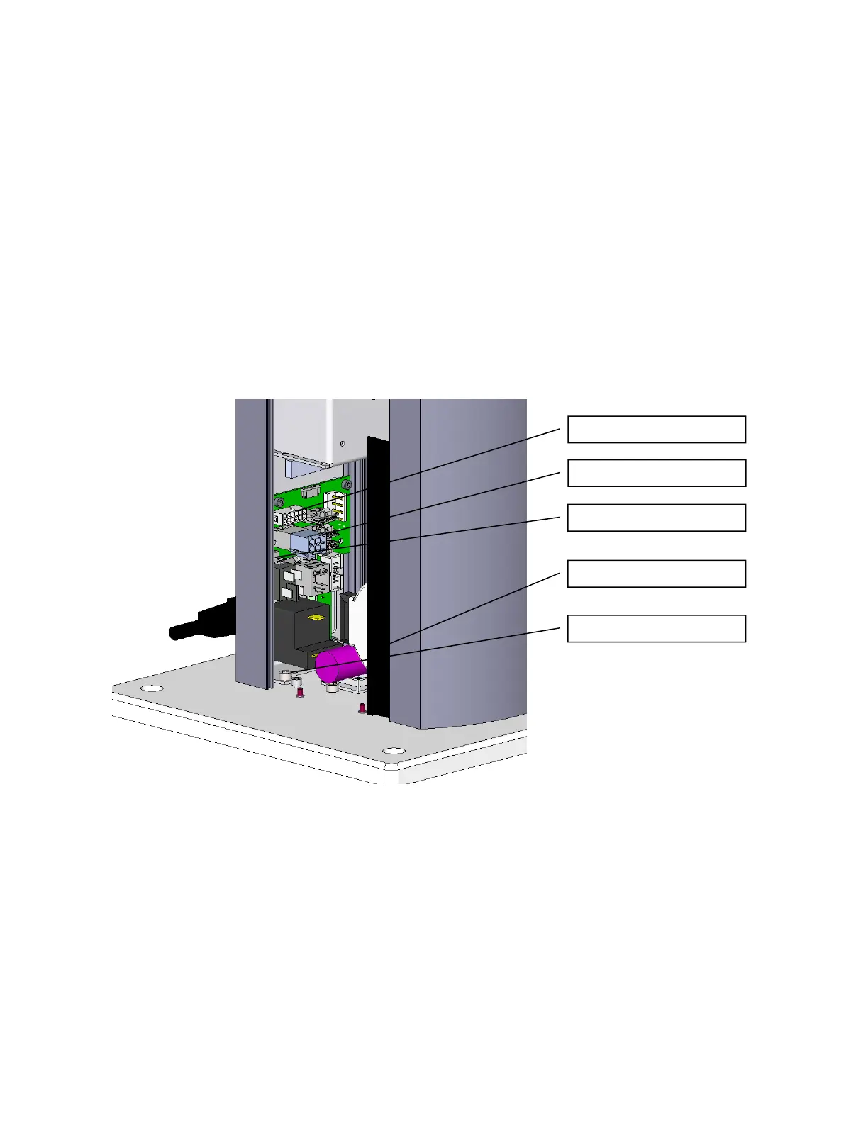
8. Unplug the Battery from the J1 Motor Interface Board.
9. Remove the screw compressing the J1 Motor Tension Spring and spring.
J1 Encoder Connector
J1 Motor Connector
Batter
Connector
S
lash Guard
E Chassis Screw