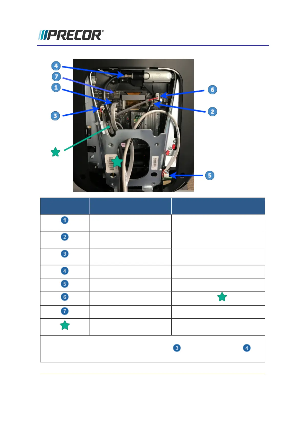
CONNECTOR
LOCATION
INTERFACE
DESCRIPTION
CONNECTOR/DEVICE
TYPE
COMM Data Cable
(1)
Black color RJ45 eight pin modular
(flat gray Data cable).
Ethernet (LAN) Cable
(1)
Silver color RJ45 eight pin modular
connector (round black LAN cable.
E-Stop Switch Cable
(TRM Only)
Six pin strip, keyed.
RF (TV) Cable with Isolator F-Type coax
HHHR Sensor Input Cable Four pin strip, keyed.
DC Input Power Two pin plug (see )
microSD mass storage .microSD memory card
Ferrite cable clamp The input power cable must be
looped thru the ferrite cable clamp.
Notes:
(1)Be careful to NOT connect the COMM Data Cable to the Ethernet input port
which can damage the CPA board.
18
4 Console Installation and Removal
Console I/O Port Diagram