37
Pre-Out
When conguring the M80 as a 7.1 or 5.1 surround system, connect the Pre-Out S/W (Subwoofer) jack to the LFE or line level input
on a powered subwoofer as shown in Diagram 7 on Page 24 and described on Page 25. (Required for 5.1 or 7.1 conguration.)
Connect the remaining Pre-Out jacks on the M80 Rear Panel to an external amplier for high output audio in large rooms or when
using speaker systems that require additional power. (Option)
7.1 System
1. Using a 7.1 audio patch cable (eight RCA-RCA plugs; or 4 identical stereo RCA-RCA patch cables) with gold ends, connect
the PRE-OUT jacks on the M80 to the appropriate line level audio INs on the external amplier(s). (A proper 7.1 Cable will
have color coded RCA plugs that match the color coding on the PRE-OUT jacks.)
2. Do not connect the S/W Out on the M80 to the amplier unless the amp is going to power the subwoofer.
3. Conrm proper connection of audio channels from the M80 to the amplier(s). Improper connections will have an ad-
verse eect on surround sound performance.
4. Connect the external amplier(s) to speakers as appropriate.
5.1 System
1. Using a 5.1 audio patch cable (six RCA-RCA plugs; or 3 identical stereo RCA-RCA patch cables) with gold ends, connect the
PRE-OUT jacks on the M80 to the appropriate line level audio INs on the external amplier(s), and do not connect the BSR
(Surround Back Right) and BSL (Surround Back Left) Out jacks on the M80 to the amplier. (A proper 5.1 Cable will have
color coded RCA plugs that match the color coding on the PRE-OUT jacks.)
2. Do not connect the S/W Out on the M80 to the amplier unless the amp is going to power the subwoofer.
3. Conrm proper connection of audio channels. Improper connections will have an adverse eect on surround sound per-
formance.
4. Connect the external amplier(s) to speakers as appropriate.
CONNECTIONS
Trigger Out
The M80 Trigger Out is a 12VDC control voltage that can
be used to turn an external device such as a powered
subwoofer (Diagram 7, Page 24) or external amplier
ON/OFF as congured in Source Setup.
There are three selectable modes in the Setup Menu/
Trigger OUT.
Source Setup - Turns the Trigger OUT ON/OFF by
source selection as congured in the Source Setup.
Main - Turns the Trigger OUT ON/OFF with M80 ON/OFF
Status.
Zone 2 - Turns the Trigger OUT ON/OFF with Zone 2
ON/OFF Status.
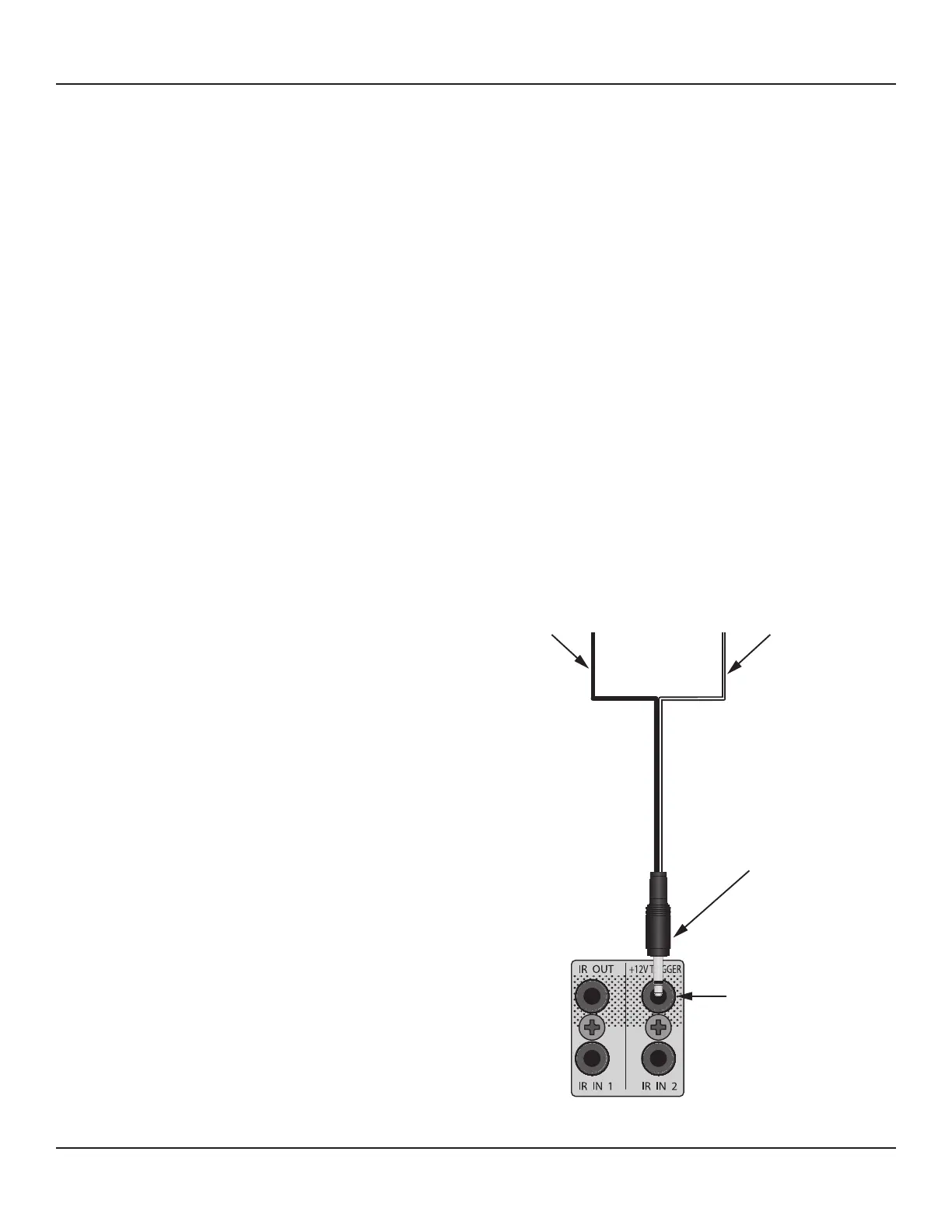
To connect the Trigger Out:
1. Using a 3.5mm mini-plug, connect the tip to the
+12VDC Control IN on the external device to be
controlled. (If using a specic connector or plug,
conrm the polarity of the device and the connec-
tor.) Diagram 20
2. Connect the 3.5mm mini plug sleeve to the Control
IN GND on the external device.
3. Conrm connection polarity.
4. Plug the mini plug into the Trigger Out on the M80.
Black
To Controlled Device
Control IN GND
White Stripe
To Controlled Device
Control IN +12VDC
M80
Trigger OUT
M80
3.5mm Mini Plug
Diagram 20 Trigger Out Connections