87
MULTIZONE CONFIGURATION
Front
Left
Front
Right
16AWG Stranded (minimum) Speaker Wire
Subwoofer
Sub
Audio IN
Sub
Control IN
RCA-RCA
Cable
(or appropriate)
Mini-Mini
Cable
(or appropriate)
IR IN
IR OUT
Center
Surround
Left
Surround
Right
Multizone
Left
Multizone
Right
CENTER
CONTROL
IN
AUDIO
IN
16AWG Stranded (minimum)
Speaker Wire
16AWG Stranded
(minimum)
Speaker Wire
White Stripe
To Positive
White Stripe
To Positive
White Stripe
To Positive
White
Stripe
To Positive
White Stripe
To Positive
White Stripe
To Positive
White Stripe
To Positive
Zone 2 (Stereo)
Main Room (5.1 Surround)
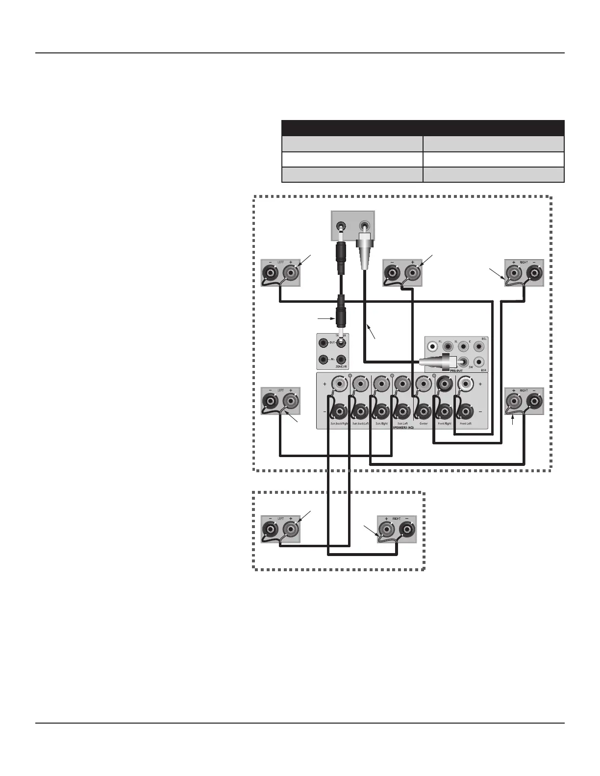
Diagram 122 Zone 2 Speaker
Connections
Speaker Wire Requirement
1. Pull 1 run of 16AWG (min) 4-conductor stranded speaker wire directly from the M80 location to each Zone 2 speaker. Leave
extra length (24 inches) on both ends to work with when making connections. Use the following Chart to determine the
proper wire gauge based on actual wire length from the M80 to the Zone 2 speakers:
SPEAKER WIRE LENGTH SPEAKER WIRE GAUGE
150' (46m) 16 AWG
400' (122m) 14 AWG
1000' (305m) 12 AWG
Video Cable Requirements
Composite Video
1. Pull 1 run of RG6 directly from the M80
location to the Zone 2 Video Display
location. Leave extra length (24 inches)
on both ends to work with when making
connections. Terminate with RCA plugs
on both ends.
S-Video
1. Pull 1 run of S-Video cable directly from
the M80 location to the Zone 2 Video
Display location. Leave extra length (24
inches) on both ends to work with when
making connections. Terminate with S-
Video plugs on both ends.
Line Level Audio Cable Requirements
1. Pull 1 run of 22AWG/2 pair shielded cable up
to 50 feet from the M80 location to the Zone
2 Video Display location. Leave extra length
(24 inches) on both ends to work with when
making connections. Terminate with RCA
plugs on both ends.
Note : It is not necessary to connect line level
audio to the Video Display if amplied audio
is being fed to Zone 2 via the M80 Surround
Back speakers or an external amplier.
IR Control Wire Requirements
1. Pull 1 run of 24AWG (min) 4-conductor un-
shielded solid or stranded copper wire up to
1200 feet from the M80 location to where the
IR receiver will be connected in Zone 2.
ZONE 2 SPEAKER CONNECTIONS
Diagram 122 shows a typical application for
connecting a stereo pair of speakers in Zone 2 to
the M80 with a 5.1 Surround conguration in the
Main Room. For other Main Room speaker congurations, see Diagram 7, Page 24.
Note: Do not connect more than one 4Ω or 8Ω speaker directly to any Speaker Terminal pair (+/-) at the same time. This will cause
the M80 to shut down and can damage the unit. This type of damage is not covered by the Warranty.
Speaker Connections
Connect speakers as described in section: Speaker Connections on Page 25.
Zone 2 Subwoofer
A subwoofer can be connected to Zone 2 by using a subwoofer with an integrated crossover network and stereo speaker connec-
tions. Connect the Surround Back Left and Right Speaker Terminals on the M80 to the Left and Right Speaker Level INs on the sub.
Connect the Zone 2 Left and Right Speakers to the sub Left and Right Speaker OUT Terminals.
Note: The subwoofer connections shown in Diagram 122 only apply to the Main Room conguration.