ConveyLinx-IO User’s Guide
Publication ERSC-1008 Rev 1.1 – October 2017
POWER CONNECTIONS
IP54 INSTALLATION
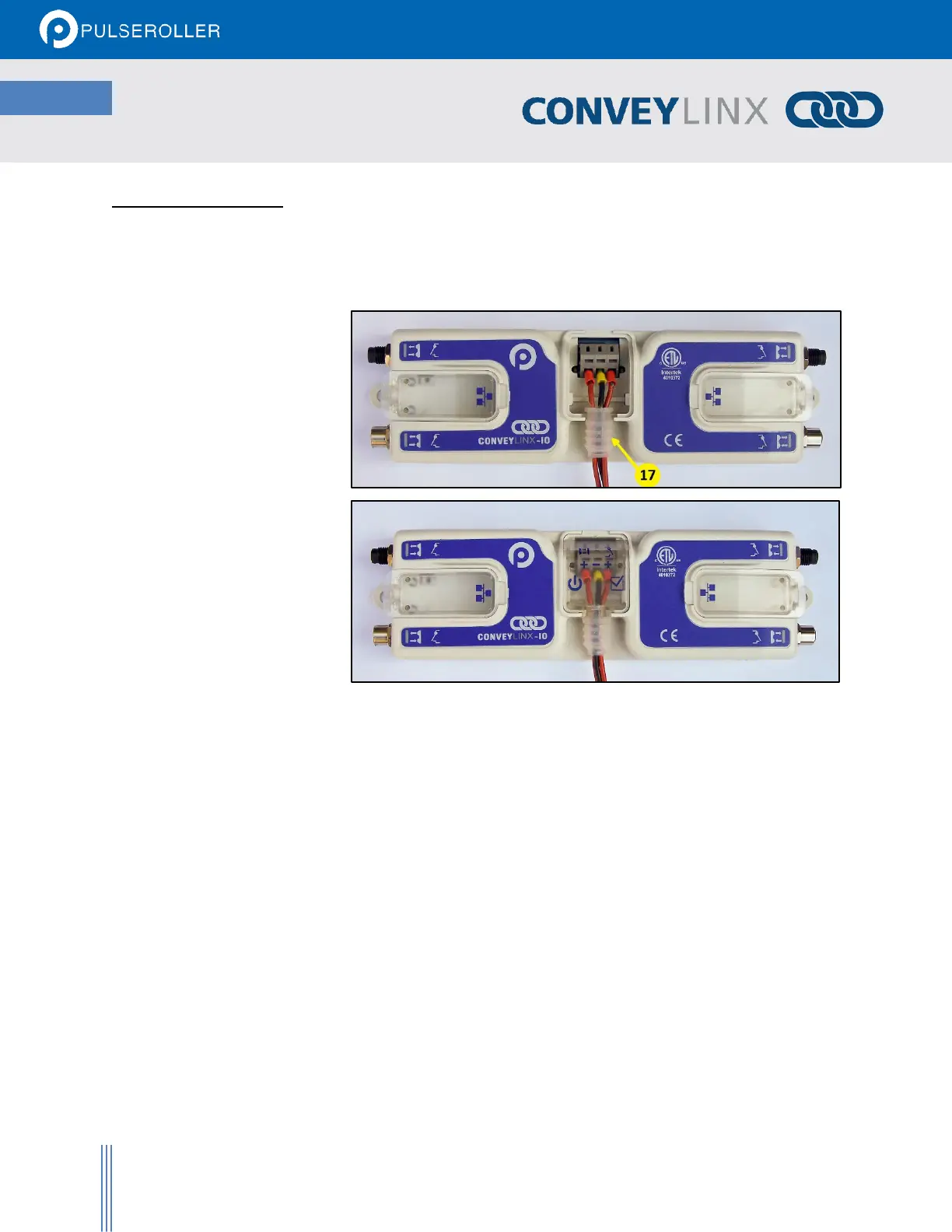
Item 17 as depicted in Figure 2 may be unattached to the module when shipped and are included in the module’s
shipping box. These items are used to maintain an IP54 installation of the power and Ethernet wiring.
Power wires are fed through the
protective shroud (Item 17). The
wire terminals are standard cage-
clamp style.
Once wiring has been completed
the power wiring compartment is
then sealed by snapping into place
the Power Compartment Cover
(Item 18).
LOGIC AND OUTPUT POWER
The ConveyLinx IO module is designed to allow for separate power connections for module logic and digital
outputs power so that these can be powered by separate power supplies. For example, the digital outputs p ower
supply can switched off by an emergency stop control system so that all output devices have power removed.
With the outputs power separately switched off; the logic power supply can remain on so that the module’s
communications can remain active and report status to networked supervisory control system(s). Figure 13 shows
a diagram for separate logic and MDR power supplies and Figure 12 shows a diagram for a single power supply for
both logic and MDR power. Note that powering the Outputs terminal also powers the Logic.