Introduction Page 37 of 37
1.5.5 Fuse Replacement
WARNING
MAKE SURE THE UNIT HAS BEEN DISCONNECTED FROM ITS AC POWER SOURCE FOR AT
LEAST FIVE MINUTES BEFORE PROCEEDING.
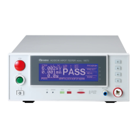
Figure 1-3: Fuse Drawer Release Tab
• Remove the fuse drawer by inserting a small flat head screwdriver behind the small tab to force the draw
outward. Refer to Figure 1-4.
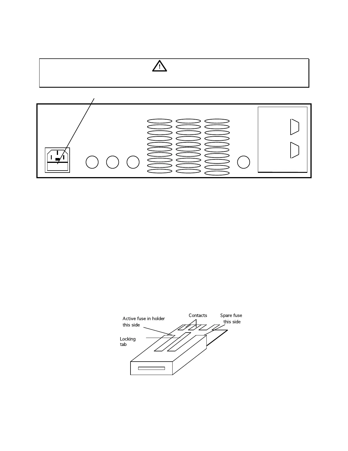
• Once the fuse drawer has been completely removed from the instrument remove the clear fuse tray from the
drawer by lifting upward slightly on the long narrow black locking tab. This will allow the fuse tray to be
removed from the fuse drawer. This tray contains the active fuse, left side (secured by holder) and spare fuse on
the right side (if present). Refer to Figure 1-4.
• Remove the active fuse from the holder by prying upward using a small flat head screwdriver. Insert the
replacement fuse into the fuse holder.
• Once the fuse has been installed in the holder and spare fuse (if desired) installed in the right side of the tray
insert the tray back into the fuse drawer, push in and lock. The two silver contacts on the fuse tray should be
positioned towards the outside.
• Once the fuse tray has been installed in the drawer, reinstall the fuse drawer back into the instrument ac inlet
module, push in and lock.
Figure 1-4: Fuse Drawer
 Loading...