Interface Page 73 of 73
Section 3: Interface
3.1 General
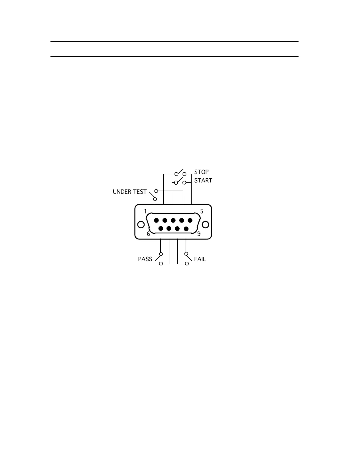
A remote control connector is located on the rear panel of the instrument with input
connections for starting and stopping the unit externally and output connections
indicating instrument status and a safety interlock connection.
Inputs require a contact closure and outputs provide a contact closure, as shown in the
figure below. Pass, Fail and Under Test relays are rated at 36V, 100mA max, 1 billion
cycles.
3.2 Remote I/O
Figure 3-1
Rear Panel Remote Connectors
The Pass and Fail outputs track the front panel PASS and FAIL indicators. After a test is
complete, either the Pass or Fail output will be asserted and the PASS or FAIL indicator
lit. When the STOP key is depressed and causes the indicators to go out the outputs also
return to the reset state. In the mode, Continue Voltage On Fail, the Fail output (but not
the Pass output) will be asserted or reset in the same manner as the FAIL indicator.
 Loading...