Raisecom
ISCOM6820-GP (A) Hardware Description
Raisecom Proprietary and Confidential
Copyright © Raisecom Technology Co., Ltd.
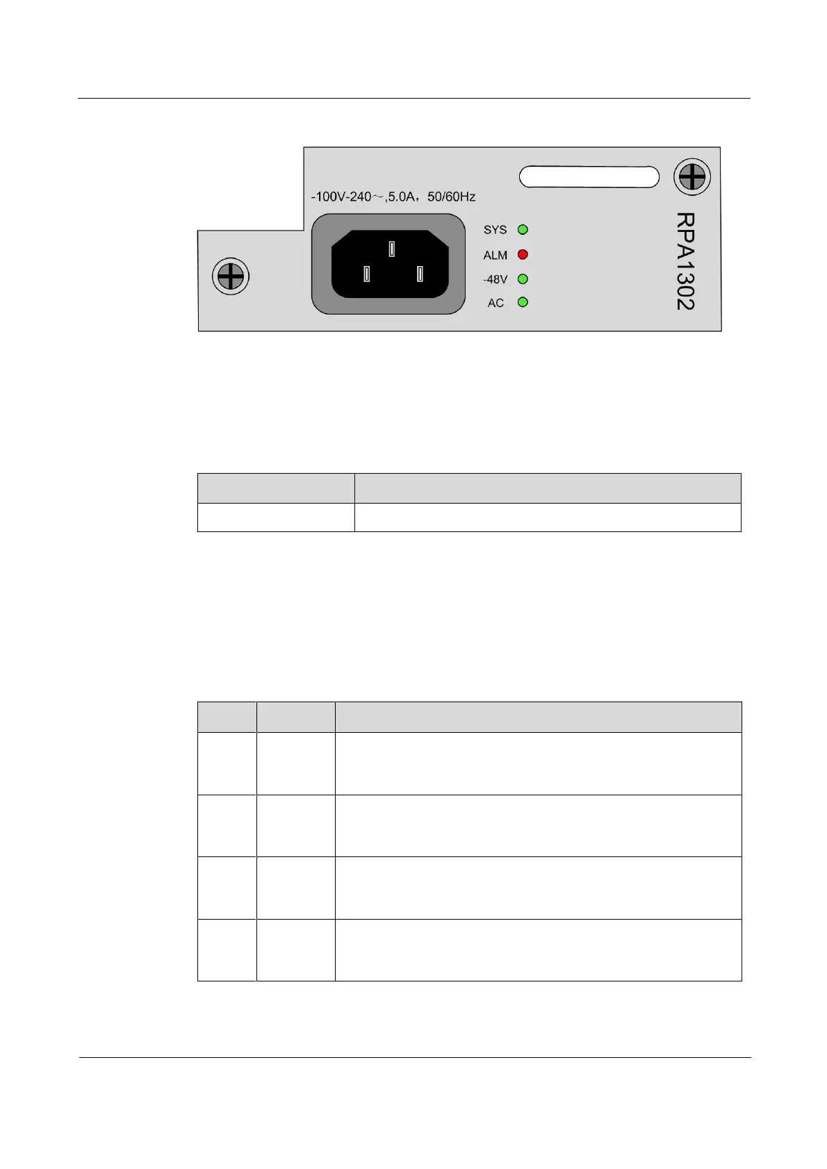
Figure 2-12 Panel of the RPA1302 power module
2.6.3 Interfaces
There is 1 interface on the RPA1302 power module.
Table 2-17 lists the interface on the RPA1302 power module.
Table 2-17 Interface on the RPA1302 power module
AC power interface/C13 connector socket
2.6.4 LEDs
There are 4 LEDs on the RPA1302 power module.
Table 2-18 lists LEDs on the RPA1302 power module.
Table 2-18 LEDs on the RPA1302 power module
Power LED
Green: the power supply is working properly.
Off: the device is powered off or powered on improperly.
Alarm LED
Green: the power supply works abnormally.
Off: the device is not powered on or powered on improperly.
Output voltage LED
Red: the device DC voltage is output normally.
Off: the device DC voltage is output abnormally.
Power input LED
Red: the device external power is input normally.
Off: the device external power is not input or input abnormally.