Raisecom
ISCOM6820-GP (A) Hardware Description
Raisecom Proprietary and Confidential
Copyright © Raisecom Technology Co., Ltd.
To connect the fiber, align the fiber head with the optical interface. Be careful not to
damage the ceramic tube inside the optical interface. After snapping the fiber in place,
rotate the screw sleeve clockwise to fasten the optical interface.
To remove the fiber, rotate the screw sleeve counterclockwise. When the screw sleeve is
loosened, pull the fiber out.
3.1.3 Wiring
Table 3-3 lists the wiring of the fiber.
Table 3-3 Wiring of the fiber
Direction of
optical signals
3.2 Ethernet cable
3.2.1 Introduction
The Ethernet cable of the ISCOM6820-GP can be used to:
Connect the Ethernet electrical interface of the ISCOM6820-GP to other devices.
Connect the SNMP of the ISCOM6820-GP to the NView NMS system.
The Ethernet interface on the ISCOM6820-GP is adaptive to straight-through cable mode and
crossover cable mode. So both kinds of Ethernet cables can be used.
The Ethernet cable needs to be made on site.
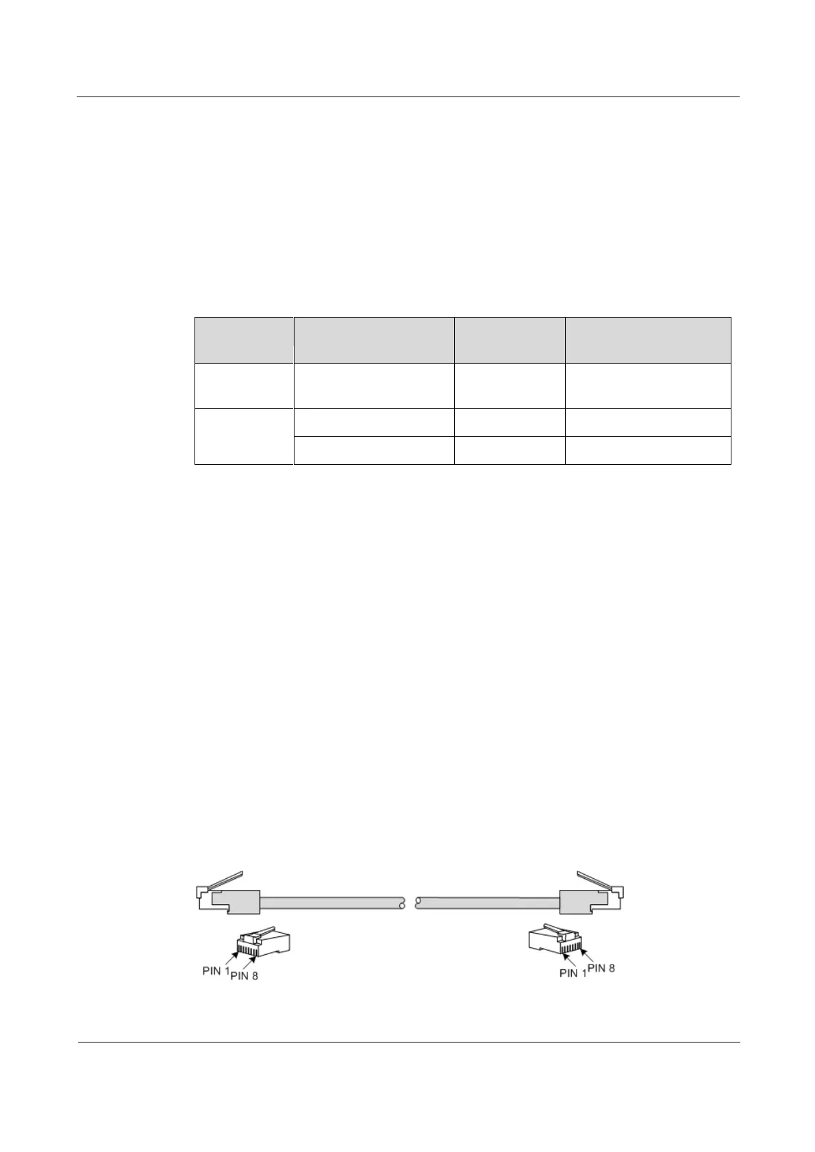
3.2.2 Appearance
Figure 3-4 shows the appearance of the Ethernet cable.
Figure 3-4 Ethernet cable