Raisecom
ISCOM6820-GP (A) Hardware Description
Raisecom Proprietary and Confidential
Copyright © Raisecom Technology Co., Ltd.
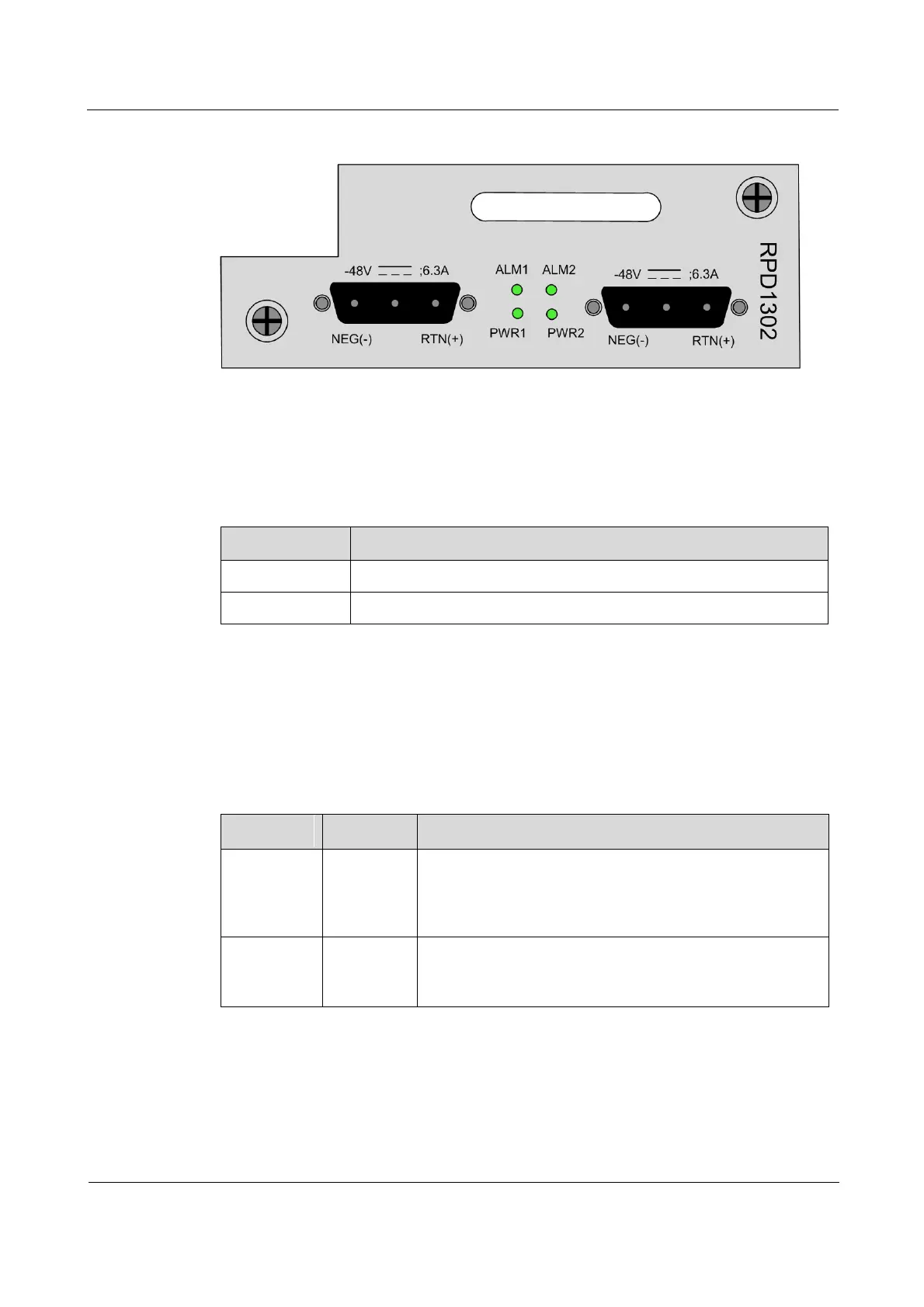
Figure 2-13 Panel of the RPD1302 power module
2.7.3 Interfaces
There are 2 interfaces on the RPD1302 power module.
Table 2-20 lists the interface on the RPD1302 power module.
Table 2-20 Interface on the RPD1302 power module
-48 V power input interface
2.7.4 LEDs
There are 4 LEDs on the RPD1302 power module.
Table 2-21 lists LEDs on the RPD1302 power module.
Table 2-21 LEDs on the RPD1302 power module
Power LED
Green: the power supply is working properly.
Off: the device is not powered on or powered on
improperly.
Alarm LED
Red: the power supply works abnormally.
Off: the device is powered off or powered on properly.
2.7.5 Technical specifications
Table 2-22 lists technical specifications of the RPD1302 power module.