EasyManua.ls Logo

Raisecom ISCOM6820-GP - Appearance; Figure 3-7 Configuration Cable; Figure 3-8 Pins and Wiring; Table 3-7 Pins of the RS-232 Interface

Raisecom ISCOM6820-GP
61 pages
Print Icon
To Next Page IconTo Next Page
To Previous Page IconTo Previous Page
Loading...
Raisecom
ISCOM6820-GP (A) Hardware Description
3 Fiber and cables
Raisecom Proprietary and Confidential
Copyright © Raisecom Technology Co., Ltd.
29
3.3.1 Appearance
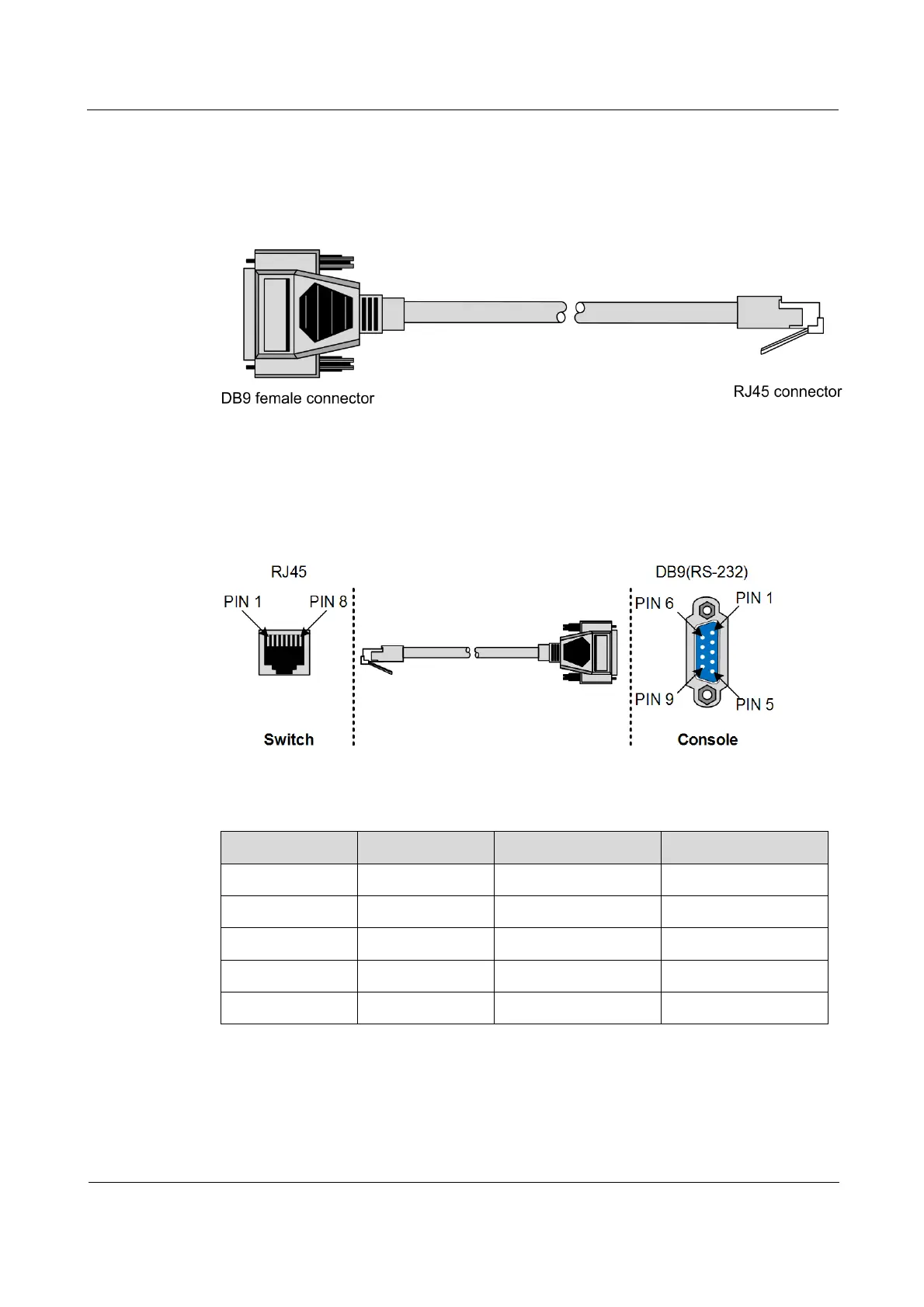
Figure 3-7 shows the appearance of the configuration cable.
Figure 3-7 Configuration cable
3.3.2 Wiring
Figure 3-8 shows the PINs and wiring of the RS-232 serial interface and RJ45 Ethernet
interface.
Figure 3-8 PINs and wiring
Table 3-7 lists PINs of the RS-232 interface.
Table 3-7 PINs of the RS-232 interface
PIN
Function
PIN
Function
PIN 1
DCD
PIN 6
DSR
PIN 2
RxD
PIN 7
RTS
PIN 3
TxD
PIN 8
CTS
PIN 4
DTR
PIN 9
RI
PIN 5
GND
Table 3-8 lists PINs of the RJ45 Ethernet interface.

Table of Contents

Other manuals for Raisecom ISCOM6820-GP

Related product manuals