COPYRIGHT © 2014 RED.COM, INC
RED DSMC OPERATION GUIDE
955-0020_V5.2, REV-G | 31
POWER OPERATIONS
This section describes the basic power operations of the DSMC system.
For more information, see the DSMC Power Operation Guide available at www.red.com/downloads.
WARNING: Modules, displays, and accessories are NOT HOT SWAPPABLE, meaning that you cannot remove or
install the item while the camera is turned on. Before installing or removing a module, display, or accessory, you
MUST turn off the camera. Failure to do so may result in damage to the item or DSMC that will not be covered
under warranty.
POWER INPUTS
1
2
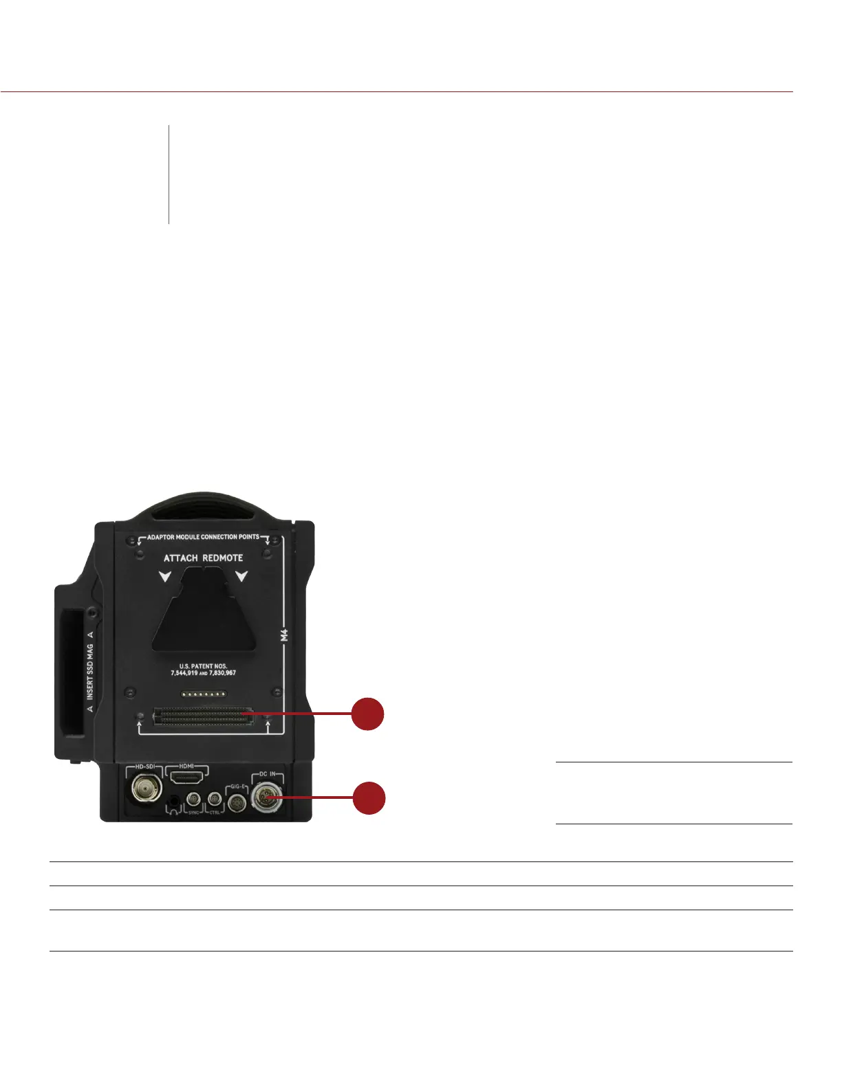
There are two (2) primary power inputs that provide power to the DSMC BRAIN:
# DSMC POWER INPUT DESCRIPTION
1 SEARAY power connector Provides power to the BRAIN from attached DSMC modules
2 DC IN connector Provides power to the BRAIN using a DSMC Power Adaptor or certain
battery modules, such as the Backpack Quickplate
NOTE: Additionally, one (1) REDVOLT battery may be used in conjunction with the DSMC Side Handle to provide
short term power and support hot-swapping of other power sources.
SEARAY Connector (top) and
DC IN Connector (bottom)
03
DSMC BASIC
OPERATIONS