COPYRIGHT © 2014 RED.COM, INC
RED DSMC OPERATION GUIDE
955-0020_V5.2, REV-G | 134
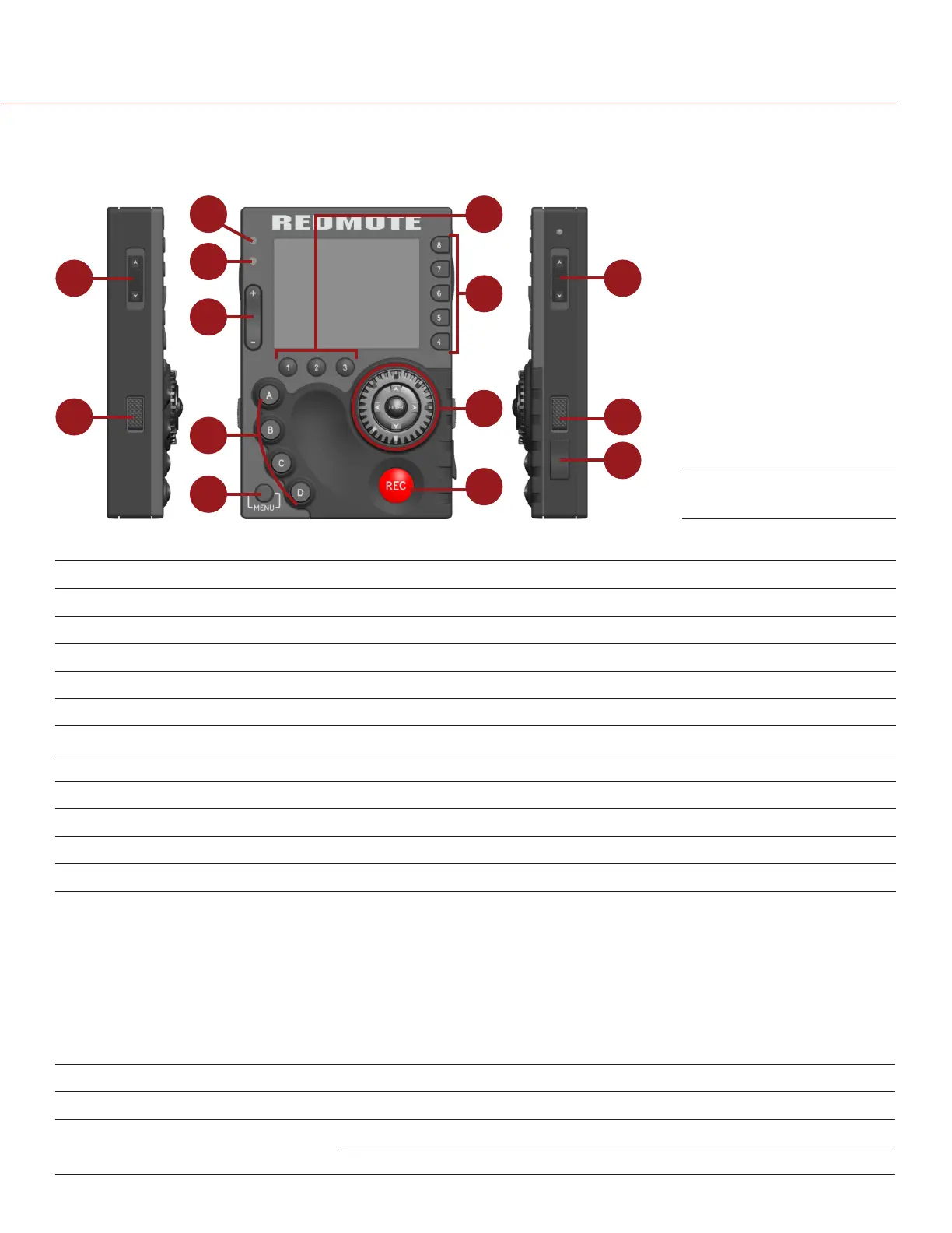
CONTROLS, CONNECTORS, AND LEDS
This section describes the REDMOTE controls, connectors, and color LCD display.
1
2
3
2
4
5
6
7
8
9
10
11
12
13
The following table describes default REDMOTE control actions. Each control is also user programmable.
# REDMOTE CONTROL DESCRIPTION
1 Stills/Motion Switch N/A; Currently disabled
2 Release Buttons Press and hold to undock the REDMOTE
5 Rocker Switch Up: Iris open; Down: Iris close
6 User Function Keys Go to “Default Key Functions” on page 191
7 Menu Button Toggle between basic and advanced DSMC menus
8 Soft Menu Buttons (1-3) Go to “Soft Menu Buttons (1-3)” on page 135
9 Soft Menu Buttons (4-8) Go to “Customize REDMOTE Setting Menus” on page 138
10 Navigation Group Go to “Navigation Group” on page 135
11 Focus/Record Button Half press initiates auto focus; full press toggles record start/stop
12 Power/Lock Switch Go to “Power/Key Lock Switch” on page 135
13 USB Power Port Charges the internal battery; upgrade firmware
For a full list of default user key actions for the REDMOTE, go to “Default Key Functions” on page 191.
COMPATIBLE CABLE
790-0230: RED Mini-USB-to-USB cable
REDMOTE LEDS
There are two (2) status LED indicators located above the rocker switch on the left side of the LCD display.
# REDMOTE LED COLOR/FLASHING DESCRIPTION
3 Power/Recording LED Red Camera startup; camera recording
4 Status/Connectivity LED Green Camera ready; REDMOTE connected
Green flashing Searching/Establishing communication
REDMOTE