RED DSMC OPERATION GUIDE: EPIC/SCARLET
COPYRIGHT © 2015 RED.COM, INC 955-0020_V6.0, REV-J | 107
GENLOCK SOURCE
Select a genlock input:
BRAIN (Default)
Rear Module (Pro I/O Module or REDCAST Module)
BRAIN GPIO
GPI Function (Camera Input): Select one (1) of the following options to configure the input for devices
connected to the SYNC connector on the BRAIN:
‒ Sync In: The camera input is used as a sync-in signal for MoCo.
‒ General Purpose In: Use the BRAIN GPI In High/Low drop-down menus to map inputs to actions.
GPO Function (Camera Output): Select an options to configure the output for devices connected to the CTRL
connector on the BRAIN:
‒ Sync Out: Provides an output sync signal to act as a shutter start tally.
‒ Recording Indicator Out: Provides a signal when recording is in process.
For more information, go to “Input/Output Connectors” on page 200.
GEN AND SYNC STATUS INDICATORS
The Lower Status Row of the camera display has GEN and SYNC indicators, which change color based on the
current genlock and sync statuses. For more information, go to “System Status Indicators” on page 58.
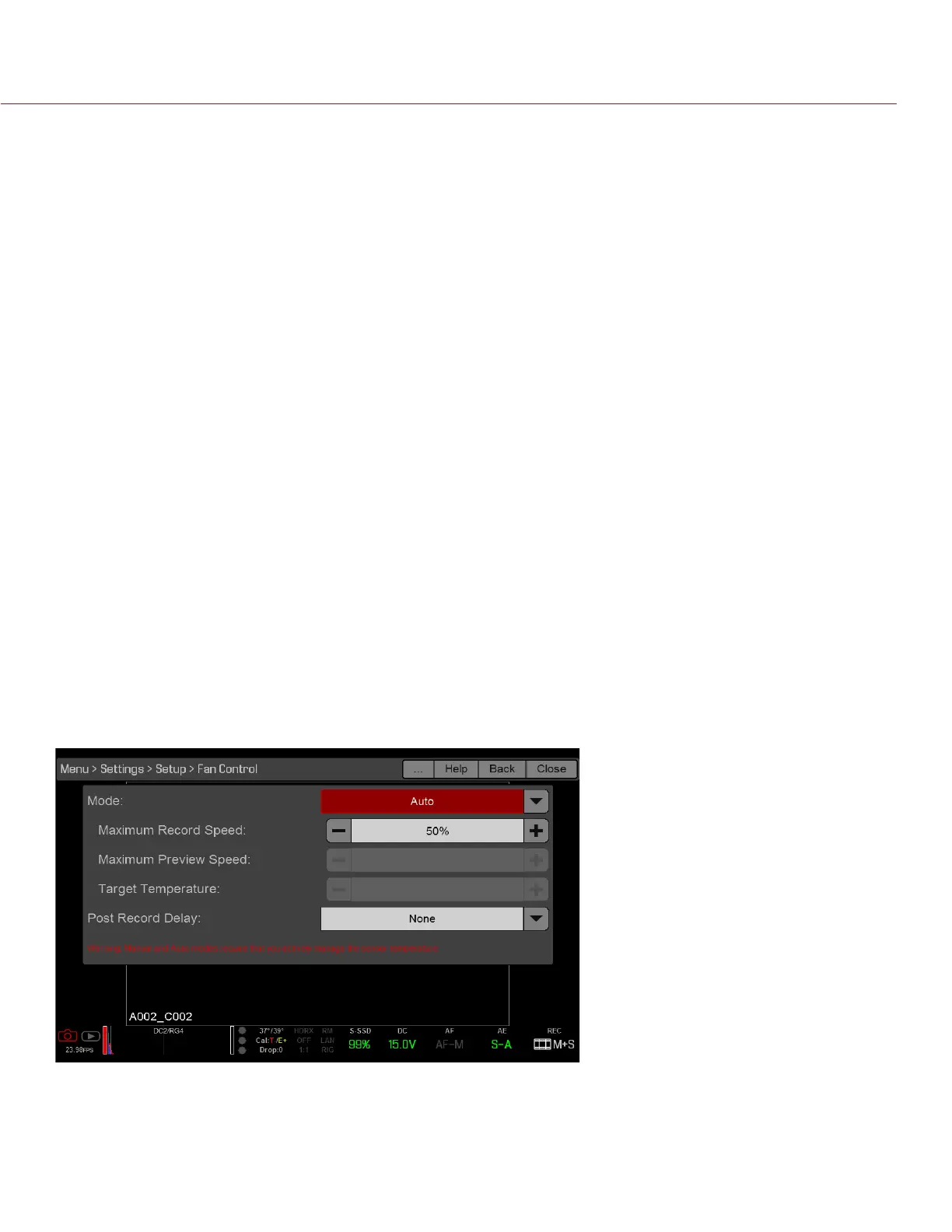
FAN AND TEMPERATURE MANAGEMENT
The DSMC is controlled by complex thermal algorithms to ensure that the sensor and camera operate at safe
temperatures. Each fan control mode affects the sensor temperature, sensor warm-up time, fan speed, and
resulting fan noise.
When selecting a fan mode, first take into consideration how each fan mode behaves, and then select a fan
mode that fits the needs of your project.
Regardless of sensor type and fan mode, you will get the best image quality by performing a black shading
calibration at the temperature you want to use for your shoot.