RED DSMC OPERATION GUIDE: EPIC/SCARLET
COPYRIGHT © 2015 RED.COM, INC 955-0020_V6.0, REV-J | 203
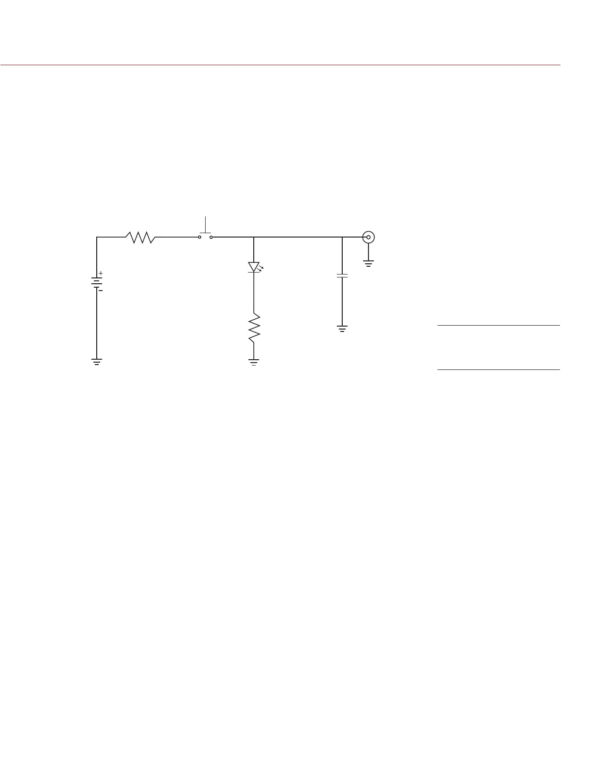
SYNC TRIGGER BUTTON CIRCUIT
The SYNC connector has a 3.3 V Schmitt trigger (5 V tolerant). The trigger is not a switch closure circuit, so it
requires that the trigger source supplies current. Both edges of the input signal may be used as a trigger.
For example, this is the behavior of the circuit when the GPI trigger is used for record start/stop:
Start Record: On ground to 3.3 V transition
During Record: Hold at 3.3 V
Stop Record: On 3.3 V to ground transition
During Stop: Hold at ground
Input Voltage:
3.3 V to 5.0 V
100 ohm
1/4 W
On when output
signal is high
10 uF
electrolytic
10 V min.
Female
BNC
Push to make/break
button/toggle
Batteries:
2x AA or AAA
3x AA or AAA
1.7 V, 20 mA
68 ohm
1/4 W
NOTE: In the diagram above, values are approximate. Use standard values.
COMPATIBLE CABLES
790-0154: 3BNC-to-00 LEMO Sync Cable
790-0187: 4-Pin 00 LEMO-to-Flying Lead
790-0415: RED Start/Stop Cable (14-Pin LEMO to SYNC, CTRL, BNC)
790-0428: RED Start/Stop Cable (14-Pin to 00B SYNC)
Trigger Button
Circuit Diagram