Installation
20 Installation Manual - Redback Smart Hybrid System - v2.0
2.5 Installing the SH5000 inverter hardware
2.5.1 OVERVIEW
The installation process is:
• Review the Packing List. Verify all parts have been supplied.
• Install the Wall Mounting Frame.
• Install BoS hardware.
• Install associated hardware.
2.5.2 WALL MOUNTING FRAME
WARNING: STRUCTURAL REQUIREMENTS!
The wall and fasteners should be suitable to secure the hung weight of the system. Please ensure that the
selected wall is made from a suitable material (e.g. solid brick) and you use at least the recommend number of
Installation notes
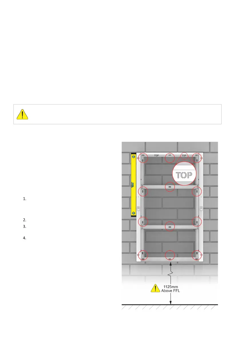
• Install the Wall Mounting Frame correctly -
observe “TOP” markings.
• The inverter is convection cooled: provide 150mm
clearance to top and sides to ensure airflow.
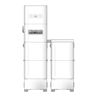
• If a BE14000 is in place, stand the frame on top of
the BE14000, and fix in position.
• Otherwise, install the frame at 1125mm above the
finished floor line (FFL): this enables easy
retrofitting of BE14000 enclosure.
Fasten the Frame to the wall.
The Wall Mounting Frame is secured by eight
fasteners at any of 16 points. Choose fastener
locations that will spread loads to the structural
part of the wall.
Use the frame as a template for fasteners.
Fix the enclosure to the wall using eight (8)
suitable fasteners.
Check the frame is level (use a spirit level). Tighten
the fasteners.


 To Next Page