Operation
44 Installation Manual - Redback Smart Hybrid System - v2.0
Inverter operation
The SH5000 has a small number of physical controls available at the inverter. All sophisticated functions are managed using
RedbackINSTALL or the Redback portal.
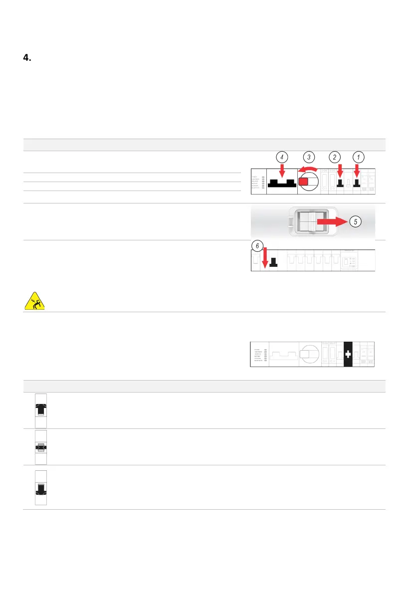
4.1 Shutdown procedure
Occasionally, it may be necessary to shut down the inverter interrupting all inverter functions, noting that PV, battery, and grid
supplies remain energised to the isolators.
Open the BoS switchgear hatch.
Switch the INVERTER AC isolator OFF (down).
Switch the BACKUP AC isolator OFF (down).
Turn the PV ARRAY DC isolator OFF (anticlockwise to 9 o’clock).
Switch the BATTERY SYSTEM DC isolator OFF (down).
At the enclosure(s) switch the Battery Isolator(s) OFF, if fitted.
Turn the Solar Supply Main Switch OFF (on the main switchboard
or sub-board).
The inverter is now OFF: all software and communications are
stopped, and no energy is being imported or exported from the
inverter.
WARNING: PV and battery supplies remain energised to the
isolators.
4.2 Bypass switch operation
The Bypass switch controls the power to the Backup AC isolator and the
EMS. Its primary use is to manually connect the backup circuit directly to
grid supply, when required.
POSITION
COMMENTS
Up
Power to the backup circuit is
from the grid supply only.
inverter no longer controls
This mode ensures grid supply to the backup circuit if the
inverter is not available or not operating reliably.
If grid supply is lost the inverter will not supply the backup
Middle
Backup circuit and EMS are
isolate
d (depowered).
No power is sent to the backup circuit.
Down
Power to the backup circuit is
supplied and managed by the
i
nverter, from any source.
This is the recommended mode of operation.
If grid supply is lost the inverter will continue to supply the
backup circuit from the batteries and PV- the entire system will
shut down when the batteries reach the minimum state of