Redback Technologies
Installation Manual - Redback Smart Hybrid System - v 2.0
49
Troubleshooting
5.1 Earth fault alarm
If the Redback system detects an earth fault:
An audible alarm will sound in the inverter.
The system error light will be solid (see next page).
An email will be sent to Redback customer service, the installer, and the system owner.
An email is also sent when the alarm is cleared.
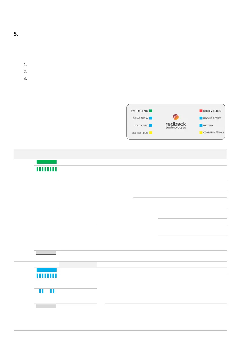
5.2 Inverter Status LEDs
The Redback inverter is equipped with an LED array to indicate
system status and aid diagnosis. The table below lists
LED
indications, probable cause
, and rectification steps. If the problem
is not solved contact Redback Technologies for assistance.
Indicates the Homeowner may complete this activity.
Indicates the activity may only be completed by an
Electrically Certified person.
MEANING AND OR
PROBABLE CAUSE
Wait up to 15 minutes after a restart- this may be normal behaviour.
The system may cycle several times during start-up. Completion of
start-up process is indicated by the LED stabilising to ON.
UTILITY GRID
LED
not
connected
Turn INVERTER AC isolator ON
(up).
The grid is available - the
inverter is not connected yet.
not installed or are
connected correctly.
Check SOLAR
ARRAY LED
Turn PV ARRAY DC isolator ON
(clockwise).
BATTERY LED
batteries are
installed.
Switch BATTERY SYSTEM DC
isolator ON
Check cables; Check battery
DIP switches; Restart
Active
At night, both arrays indicate Not Active.
If only one array is installed, the other array will indicate as Not Active.
During daylight, perform the following checks if a connected array
indicates as Not Active:
Active
Active
Active
Ensure PV ARRAY DC isolator is ON (clockwise to 12 o’clock).
Ensure PV cables are correctly connected to the inverter
(pairing & polarity).
Ensure that solar output is within the capabilities of the MPPT
trackers i.e., 125 – 550V DC @ 11A/array.