4 Installation Manual - Redback Smart Hybrid System - v2.0
Contents
Know your product ................................................................................................................................. 7
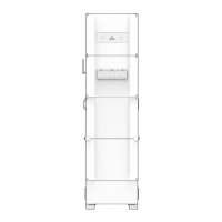
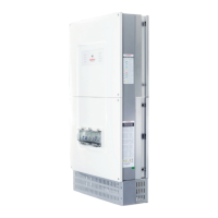
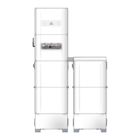
1.1 Major components .............................................................................................................................. 7
1.2 Dimensions and weights ...................................................................................................................... 8
1.3 Installation space ................................................................................................................................. 8
1.4 Compatibility and limitations ............................................................................................................... 9
1.5 Backup circuit design notes ................................................................................................................. 9
Installation ........................................................................................................................................... 10
2.1 Installation overview.......................................................................................................................... 12
2.1.1 Before you go to site ............................................................................................................ 12
2.1.2 At site ................................................................................................................................... 13
2.2 Guide to AS5139 installation requirements for BE14000 ................................................................... 14
2.2.1 Installation on an exit path .................................................................................................. 14
2.2.2 Installation on a blank wall .................................................................................................. 15
2.2.3 Installation near a corner ..................................................................................................... 15
2.2.4 Installation with a low ceiling ............................................................................................... 16
2.2.5 Installation near a corner, with low ceiling .......................................................................... 16
2.3 Preliminary electrical installation ....................................................................................................... 17
2.4 Installing the BE14000 Battery Enclosure .......................................................................................... 18
2.4.1 Overview .............................................................................................................................. 18
2.4.2 Pre-assembly ........................................................................................................................ 18
2.4.3 Installation ........................................................................................................................... 19
2.5 Installing the SH5000 inverter hardware ........................................................................................... 20
2.5.1 Overview .............................................................................................................................. 20
2.5.2 Wall Mounting frame ........................................................................................................... 20
2.5.3 Balance of System (BoS) ....................................................................................................... 21
2.6 Inverter electrical connections .......................................................................................................... 22
2.6.1 Overview .............................................................................................................................. 22
2.6.2 Solar array connections ....................................................................................................... 23
2.6.3 Single-phase grid connection ............................................................................................... 24
2.6.4 Non-standard installation .................................................................................................... 25
2.7 Installing the Energy Meter & CTs ...................................................................................................... 26
2.7.1 Overview .............................................................................................................................. 26
2.7.2 Installation notes ................................................................................................................. 26
2.7.3 Meter Installation on a DIN rail ............................................................................................ 26
2.7.4 One, two or three phase installations .................................................................................. 27
2.7.5 AC-coupled configuration .................................................................................................... 28
2.8 Inverter communications connections .............................................................................................. 29
2.8.1 Energy meter ....................................................................................................................... 29
2.8.2 Ethernet (recommended) .................................................................................................... 29
2.8.3 DRED .................................................................................................................................... 29