“LockOut” output
This signal controls the guard lock electromagnet and can assume LL0 and LL1 value.
“ErrorOut” output
If enabled, when this signal is set to LL1 it indicates an error in the control of the guard lock. It is
set to LL0 when no errors have occurred.
Operation: general description
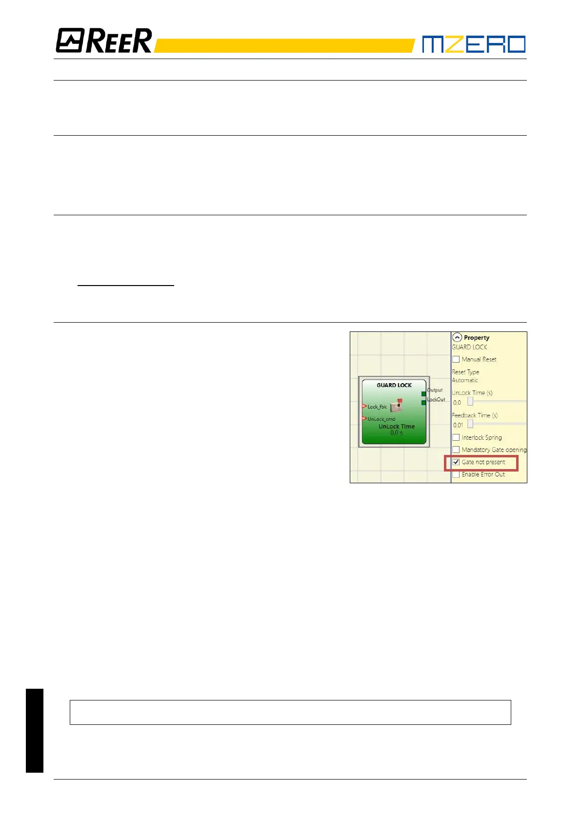
The “Guard Lock” operator analyses consistency between the status of the “Unlock_cmd” signal,
the status of a door/gate (E-GATE), if present, via the “Gate” signal, and the status of the
electromagnet via the “Lock_fbk” signal. The main output, “Output”, is LL1 (TRUE) when the guard
lock is closed and locked.
Operation in the “no Gate” mode
In this case, the user must select the “Gate not present”
parameter.
The Lock_Fbk input must always be connected to a
“LOCK FEEDBACK” input element (see the LOCK
FEEDBACK section on page 46) that verifies the status
of the guard lock electromagnet.
The UnLock_cmd input can be connected freely in the
diagram and determines the request to unlock the guard
lock (when set to LL1).
The Output signal is LL1 (TRUE) if the safety guard is
locked. When an unlock command is applied to the
UnLock_cmd input, the Output signal is set to LL0 and the guard lock is unlocked via the LockOut
signal.
The Output signal can also be set to LL0 (FALSE) when error conditions are present.
(e.g. Feedback Time exceeding the maximum allowed, etc.).
When the Unlock_cmd signal is detected, the LockOut signal unlocks the guard lock after the
UnLock Time, a parameter that can be defined by the user.
The time after which the electromagnet is activated depends entirely on the technical/physical
characteristics of the specific device and may therefore vary according to the type of guard lock
used. Thus, since the LockOut signal controls the activation of this device, the status of the
Lock_Fbk feedback signal will change at different times, depending on the type of guard lock.
This variability can be avoided by changing the value of the Feedback Time parameter, which is the
maximum delay accepted by the “Guard_Lock” operator before the Lock_Fbk signal switches
status following a request to activate the electromagnet. Clearly, the following condition must be
met:
Feedback Time ≥ Electromagnet activation time
This will now be explained using a practical example.