Example of operation in the “no Gate” mode
The guard lock used in the example continues to be locked when the electromagnet is not
energised. Hence the "Interlock spring" option must be selected.
The user unlocks the guard lock with the “SWITCH” block. The “LockOut” signal controls a
“STATUS” SIL 1/PL c output block that controls the guard lock electromagnet, the status of which
is detected by the “Lock_fbk” input via the “LOCK FEEDBACK” input block. “Output1” indicates
the status of the operations.
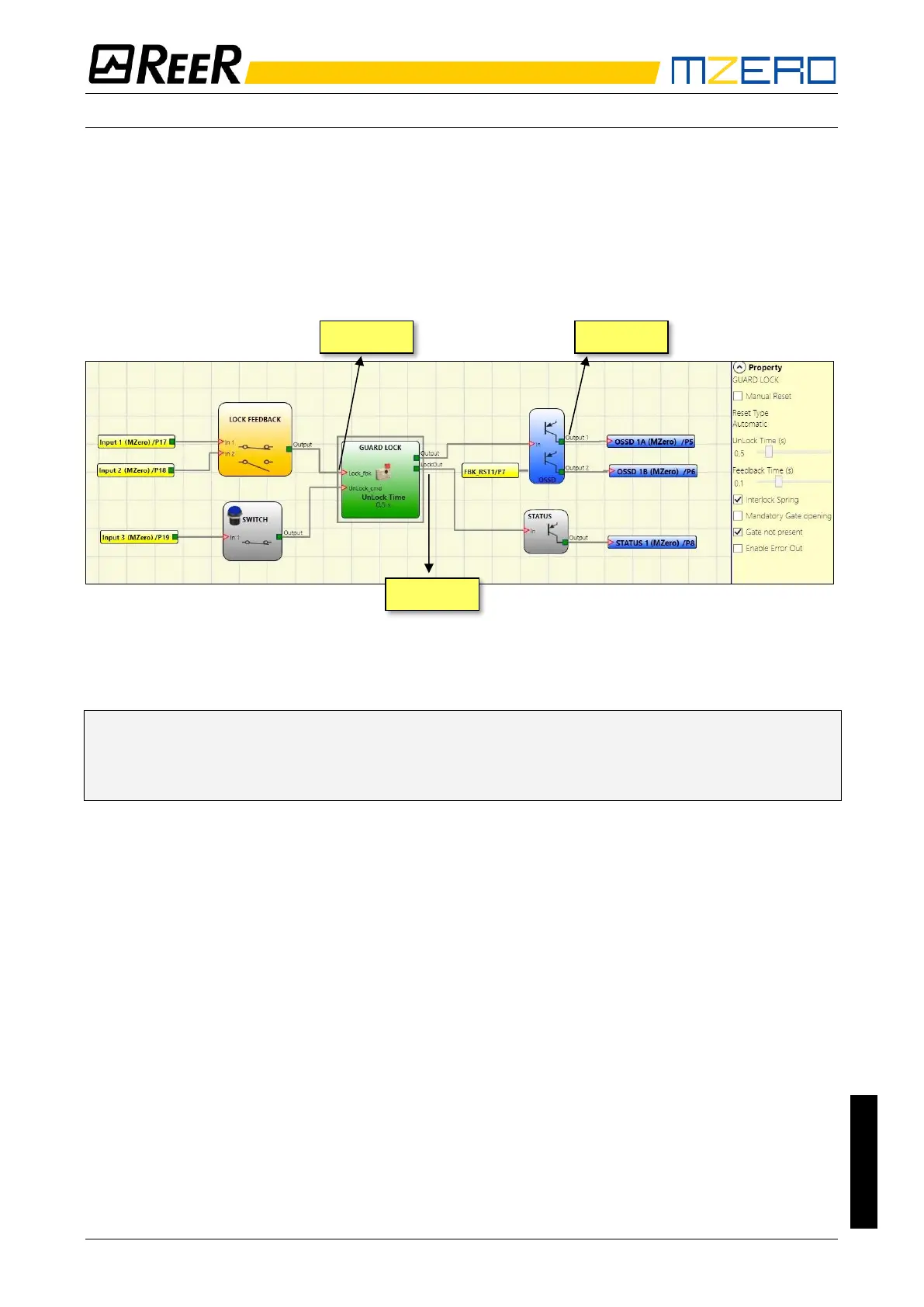
Figure 33 – Example of operation in the no Gate mode
➔ The Guard Lock operator parameters are shown on the right. On the left there is an example
of an application diagram. The electromagnet feedback consists of two contacts, one
normally closed and one normally open. When the electromagnet is energised the two
contacts switch status.
Figure 34 shows the traces relative to the operation. These are described in detail below:
(1) At this time the user requests to unlock the guard lock. The “COMMAND” signal switches
from LL0 to LL1, and the “OUTPUT1” signal switches from LL1 to LL0.
(2) At this time the electromagnet is activated with a delay of "Unlock Time", after the
command is sent. This delay has been set to 0.5 seconds. The “ACTIV.” signal switches from
LL0 to LL1.
(3) At this time the electromagnet is actually activated, 95ms after the command was sent.
This delay is due to the technical characteristics of the electromagnet. In any case, 95ms is
less than 100ms ("Feedback Time") and so no errors have occurred.
(4) At this time the user releases the unlock command and the “COMMAND” signal switches
from LL1 to LL0 as does the “ACTIV.” activation signal.
(5) At this time the electromagnet is actually deactivated, approx. 95ms after the command
was sent due to the technical characteristics of the device. The guard lock is now locked.
(6) As soon as the “Guard Lock” operator detects that the guard lock is locked, the “OUTPUT1”
signal switches to LL1.