R8C/20 Group, R8C/21 Group 12. Interrupts
Rev.2.00 Aug 27, 2008 Page 98 of 458
REJ09B0250-0200
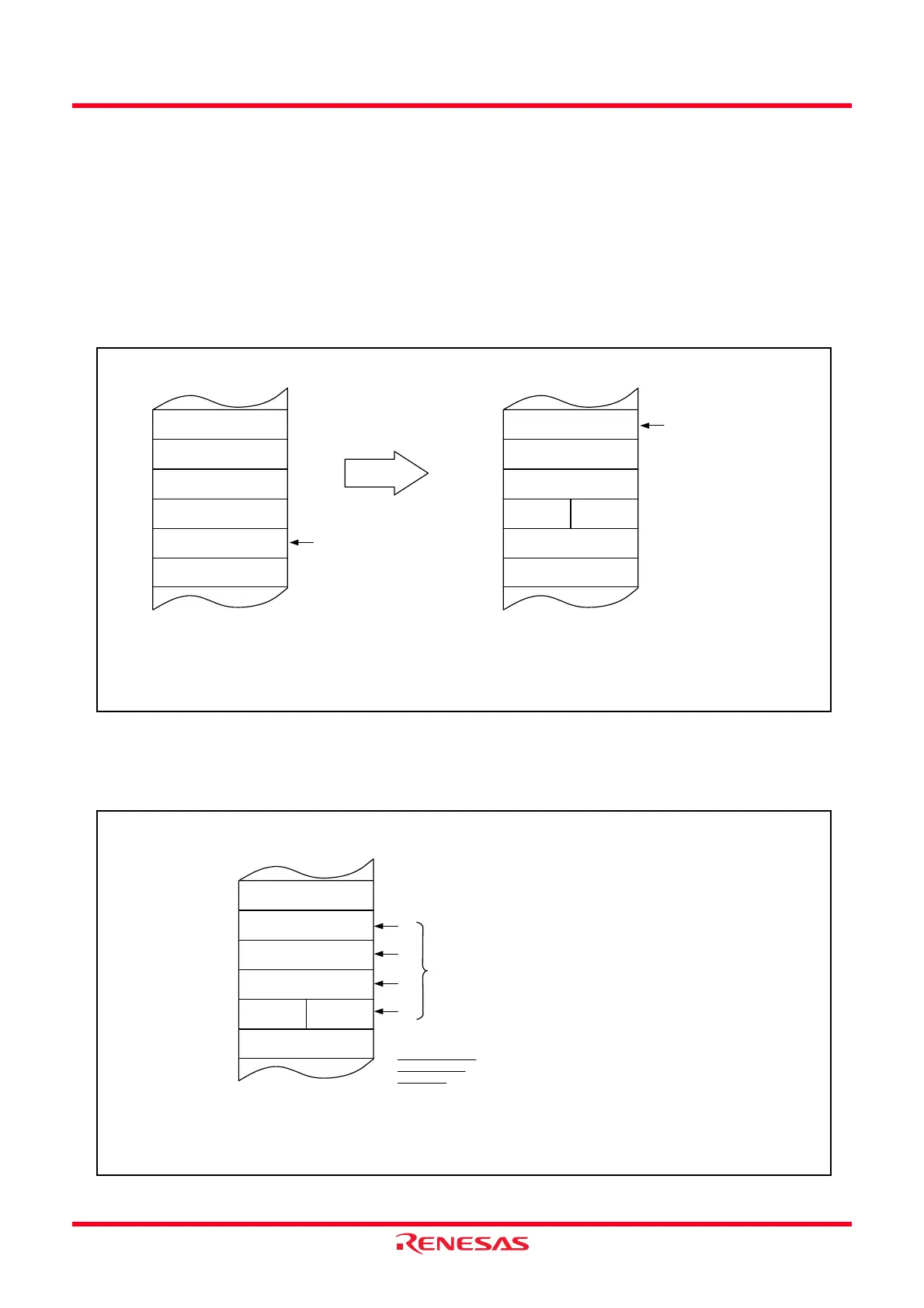
12.1.6.7 Saving a Register
In the interrupt sequence, the FLG register and PC are saved to the stack.
After 4 high-order bits in the PC and 4 high-order (IPL) and 8 low-order bits in the FLG register, extended to
16 bits, are saved to the stack, the 16 low-order bits in the PC are saved.
Figure 12.8 shows the Stack State Before and After Acknowledgement of Interrupt Request.
The other necessary registers are saved by a program at the beginning of the interrupt routine. The PUSHM
instruction can save several registers in the register bank being currently used
(1)
with 1 instruction.
NOTE:
1. Selectable from the R0, R1, R2, R3, A0, A1, SB and FB registers.
Figure 12.8 Stack State Before and After Acknowledgement of Interrupt Request
The register saving operation which is performed in the interrupt sequence is saved in 8 bits every 4 steps.
Figure 12.9 shows the Register Saving Operation.
Figure 12.9 Register Saving Operation
Stack
[SP]
SP value before
interrupt is generated
Content of previous stack
LSBMSB
Address
Content of previous stack
m−4
m−3
m−2
m−1
m
m+1
Stack state before interrupt request
is acknowledged
[SP]
New SP value
Content of previous stack
LSBMSB
Content of previous stack
m
m+1
Stack state after interrupt request
is acknowledged
PCL
PCM
FLGL
FLGH PCH
m−4
m−3
m−2
m−1
Stack
Address
PCH : High-order 4 bits of PC
PCM : Middle-order 8 bits of PC
PCL : Low-order 8 bits of PC
FLGH : High-order 4 bits of FLG
FLGL : Low-order 8 bits of FLG
NOTE:
1. When executing the software number 32 to 63 INT instructions, this
SP is specified by the U flag. Otherwise it is ISP.
Stack
Completed saving
registers in four
operations.
Address
[SP]−5
[SP]
PCL
PCM
FLGL
FLGH PCH
(3)
(4)
(1)
(2)
Saved, 8 bits at a time
Sequence in which
order registers are
saved
NOTE:
1. [SP] indicates the initial value of the SP when interrupt request is acknowledged.
After registers are saved, the SP content is [SP] minus 4.
When executing the
software number 32 to 63 INT instructions, this SP is specified by the
U flag. Otherwise it is ISP.
[SP]−4
[SP]−3
[SP]−2
[SP]−1
PCH : High-order 4 bits of PC
PCM : Middle-order 8 bits of PC
PCL : Low-order 8 bits of PC
FLGH : High-order 4 bits of FLG
FLGL : Low-order 8 bits of FLG
 Loading...