R8C/20 Group, R8C/21 Group 19. Flash Memory
Rev.2.00 Aug 27, 2008 Page 395 of 458
REJ09B0250-0200
19.4.3.5 Block Erase
If writing 20h in the first bus cycle and D0h to the given address of a block in the second bus cycle, and an auto
erase operation (erase and verify) will start.
The FMR00 bit in the FMR0 register can determine whether auto erasing has completed.
The FMR00 bit is set to 0 during auto erasing and set to 1 when auto erasing completes.
The FMR07 bit in the FMR0 register can determine the result of auto erasing after auto erasing has completed.
(Refer to 19.4.5 Full Status Check)
When the FMR02 bit in the FMR0 register is set to 0 (disable rewriting) or the FMR02 bit is set to 1 (rewrite
enables) and the FMR15 bit in the FMR1 register is set to 1 (disable rewriting), the block erase command on
block 0 is not acknowledged. When the FMR16 bit is set to 1 (disable rewriting), the block erase command on
block 1 is not acknowledged.
Do not use the block erase command during program-suspend.
Figure 19.14 shows the Block Erase Command (When Erase-Suspend Function Disabled). Figure 19.15 shows
the Block Erase Command (When Erase-Suspend Function Enabled).
In EW1 mode, do not execute this command on any address at which the rewrite control program is allocated.
In EW0 mode, the MCU enters read status register mode at the same time auto erasing starts and the status
register can be read. The status register bit 7 (SR7) is set to 0 at the same time auto erasing starts and set back to
1 when auto erasing completes. In this case, the MCU remains in read status register mode until the read array
command is written next.
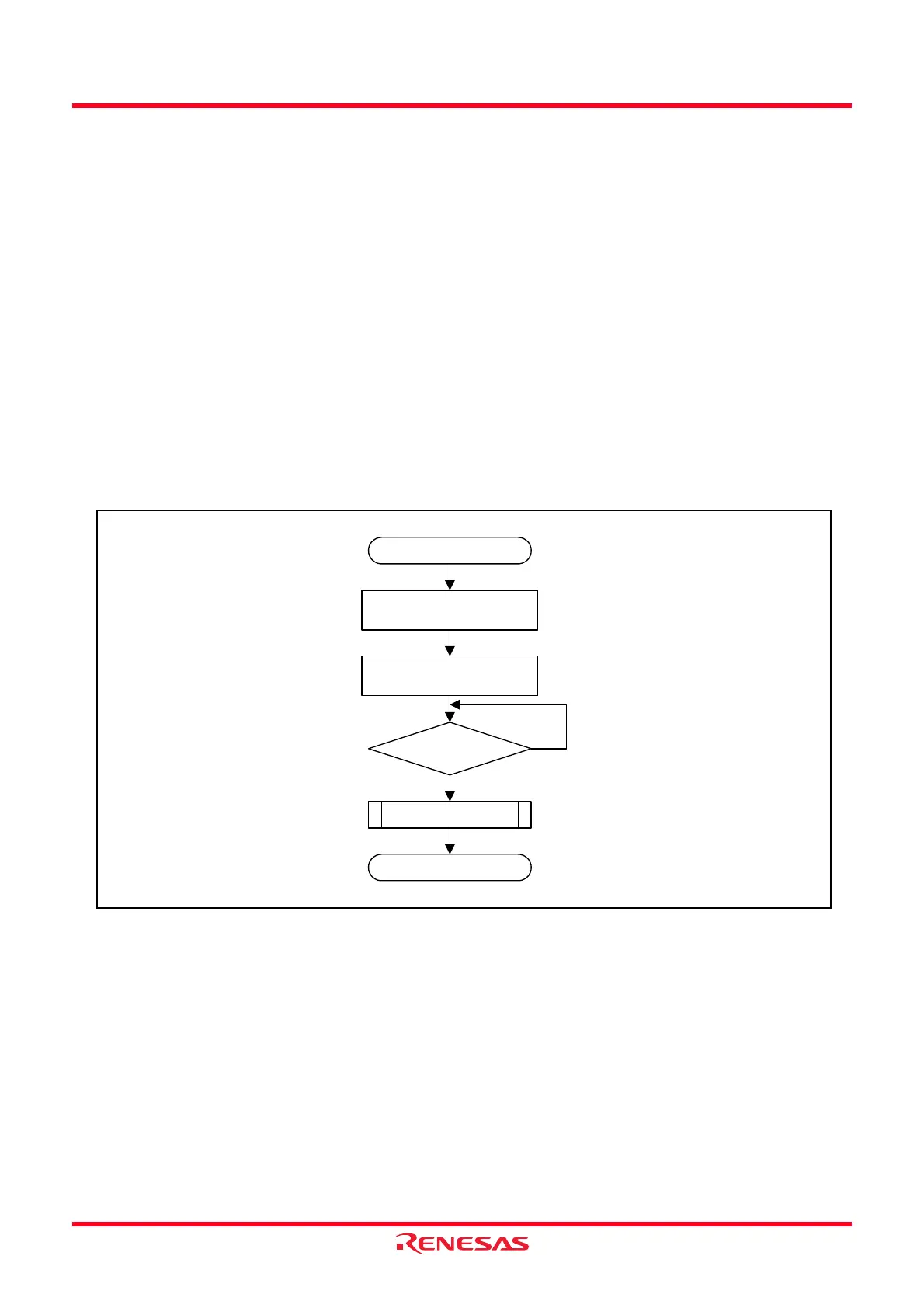
Figure 19.14 Block Erase Command (When Erase-Suspend Function Disabled)
Start
Write the command code 20h
Write ‘D0h’ to the given block
address
FMR00 = 1?
Full status check
Block erase completed
No
Yes
 Loading...