12
eRev. 1.08/15/2023
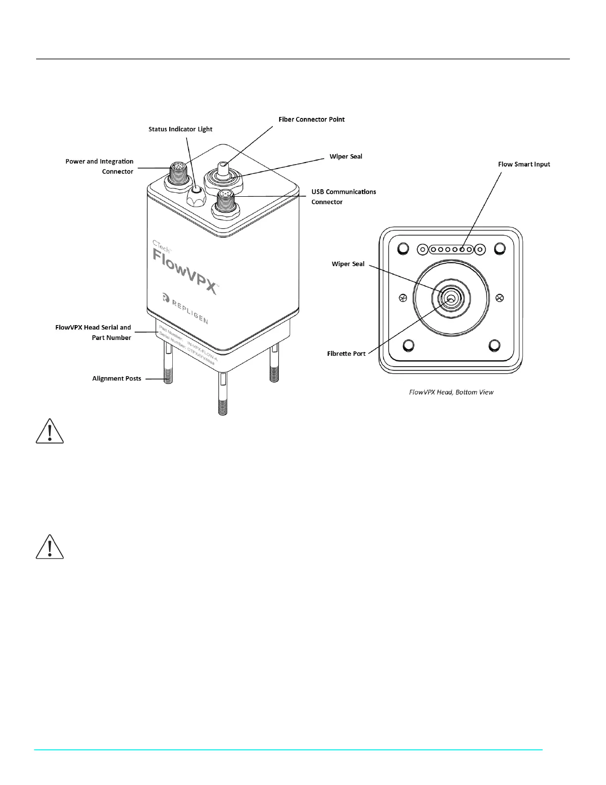
5.2 FlowVPX Head
Figure 2. FlowVPX Head Components
5.2.1 FlowVPX Status Indicator Light
The status indicator light changes color based on certain criteria.
Green, steady: Instrument powered
Green and blue, blinking: Instrument moving/reading
5.2.2 Power and Integration Connector
Connects FlowVPX instrument to power supply and allows communication to and from the FlowVPX instrument with process
automation systems.
Signal output on this connector is sent in the range of 0–5 VDC and/or 4–20 mA. This range can be configured in ViPER during I/O
configuration.
5.2.3 USB Communications Connector
Connects FlowVPX instrument to the computer for control with ViPER ANLYTX Software.
CAUTION: Avoid contact between the rubber wiper seals and sharp objects, as this may impact sealing operation around
reciprocating shaft.
CAUTION: Avoid exposure of the indicator LED housing to harsh chemicals, as it may discolor or add cloudiness to the
housing. Acceptable cleaning agents include 0.5M NaOH, de-ionized (DI) water, and 70% isopropyl alcohol.
Contact Repligen for further inquiries.