28
eRev. 1.08/15/2023
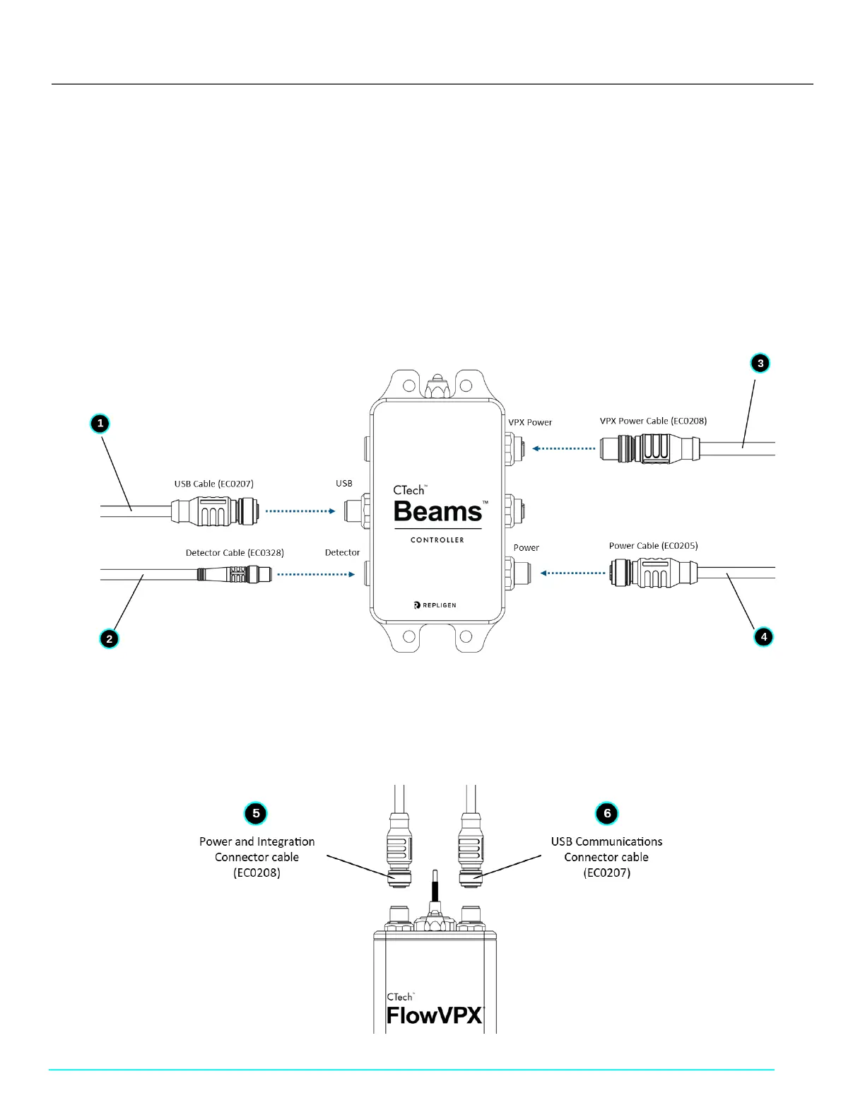
9. Connecting FlowVPX Instrument to Beams System and Computer
If using the Cary 60, see section 8 above.
1. Connect the USB Cable (EC0207) to the labeled position on the Beams Controller by aligning the pins of the plug with the
connector (see Figure 32).
2. Connect the Detector Cable (EC0328) to the labeled position on the Beams Controller.
3. Connect the VPX Power Cable (EC0208) to the labeled position on the Beams Controller.
Note: Do not connect the other end of the cable until the Detector is loaded.
4. Connect the power cable (EC0205) to the labeled position on the Beams Controller.
Figure 32. System Setup: Beams Controller Connections
5. Connect the Power and I/O Splitter Cable (EC0208) to the labeled “Power and I/O” Connector point on top of the FlowVPX
unit (Figure 33).
6. Connect the FlowVPX USB Cable (EC0207) to the labeled connection point on top of the FlowVPX unit.
Figure 33. System Setup: FlowVPX Connections