35
eRev. 1.08/15/2023
• Tighten to 40 in-lbs with the provided torque wrench.
• Tighten in a diagonal pattern to equally distribute the torque.
5. Make sure that the Flow Cell has been loaded, then click Start Detection.
6. Wait for ViPER to detect the Flow Cell. The software will indicate “VPX has detected Flow Cell.”
• Click Step Completed.
7. Orient the FlowVPX Head in an upright position and ensure the Mounting Post Clamp Handle is tightened.
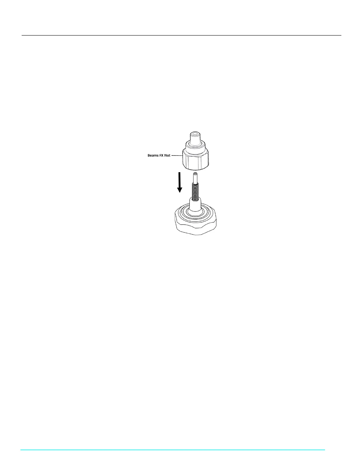
8. Place and hand-tighten the Beams FX Nut onto the threaded end of the Fibrette Optical Component, located on top of the
FlowVPX unit (see Figure 44).
• Tighten to 12 in-lbs with the provided torque wrench until there is an audible click.
Figure 44. Correct Beams FX connector Nut Orientation
9. Connect the yellow end of the Beams Source cable to the labeled position on the Beams controller.
10. Place the Beams light source on top of the tightened FX connector nut and hand-tighten the locking ring at the base of the
Beams source.
11. Click Locate Zero.
12. Wait for ViPER to find the Zero Position.
13. Click Next Step.
14. Connect the right-angle plug of the Beams Detector Cable (EC0328) to the Detector. Ensure the Detector Cable cord is
extended upwards from the detector.
15. Click Step Completed.
16. Wait for the Flow Cell Loading Transmission Test Results to appear on the screen.
17. Click OK.
10.2 Unloading the Flow Cell
1. Click the Unload button in the Instrument Control menu.