25
eRev. 1.08/15/2023
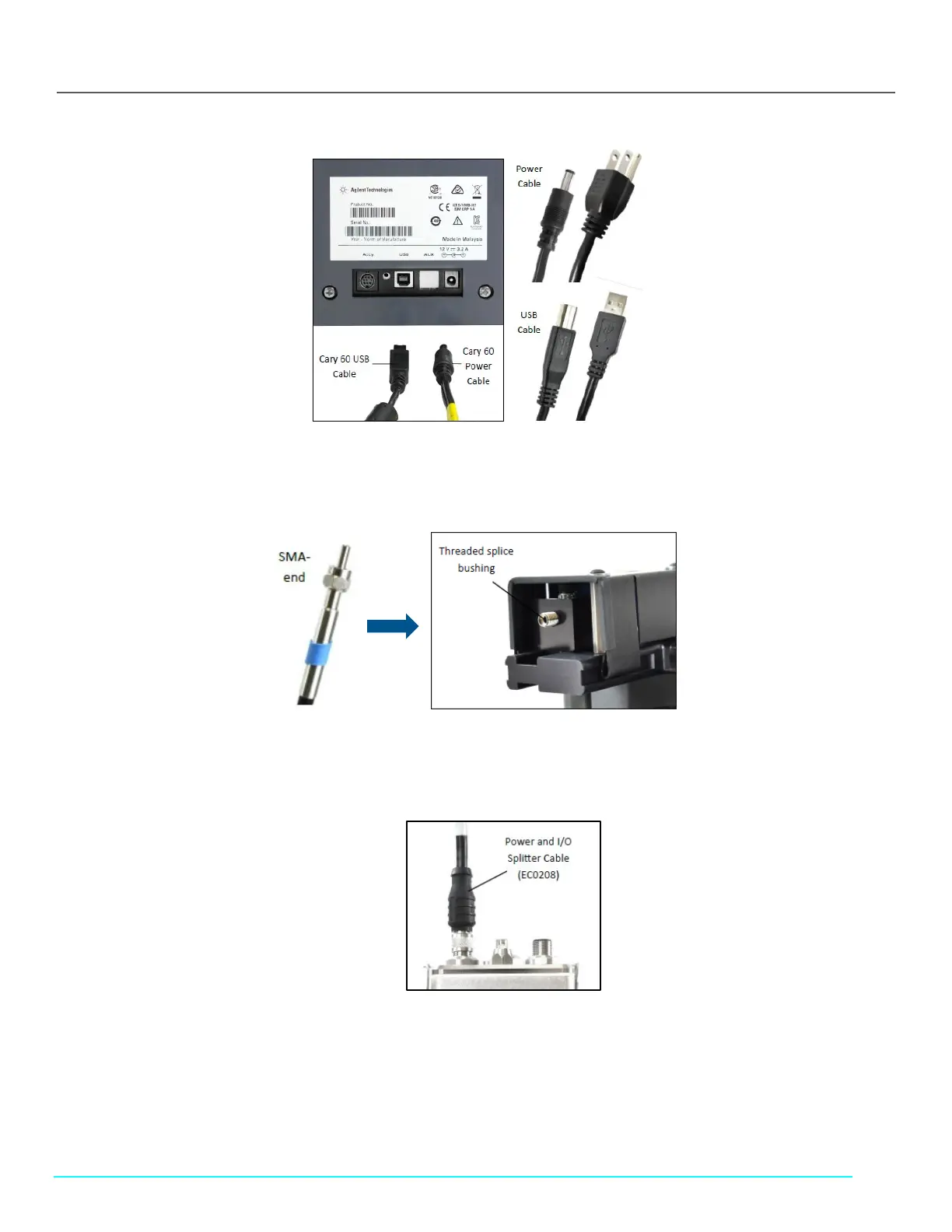
Figure 25. Cary 60 Power Cable and USB Cable, Back Panel
5. Connect the SMA end of the Delivery Fiber to the threaded splice bushing at the back of the Fiber Optic Coupler (Figure 26).
Use the hex nut to securely tighten the connection.
Figure 26. Fiber Optic Coupler Threaded Splice Bushing
6. Connect the FlowVPX Power and I/O Splitter Cable (EC0208) to the top of the FlowVPX Head (Figure 27). The FlowVPX
Extender Power Cable (EC0206) may be installed between EC0205 and EC0208 as needed.
Figure 27. Connect Power and I/O Splitter Cable (EC0208) to FlowVPX Head
7. To utilize the FlowVPX I/O connections, connect the I/O External Cable (EC0214) to the Power and I/O Splitter Cable (Figure
27).