26
eRev. 1.08/15/2023
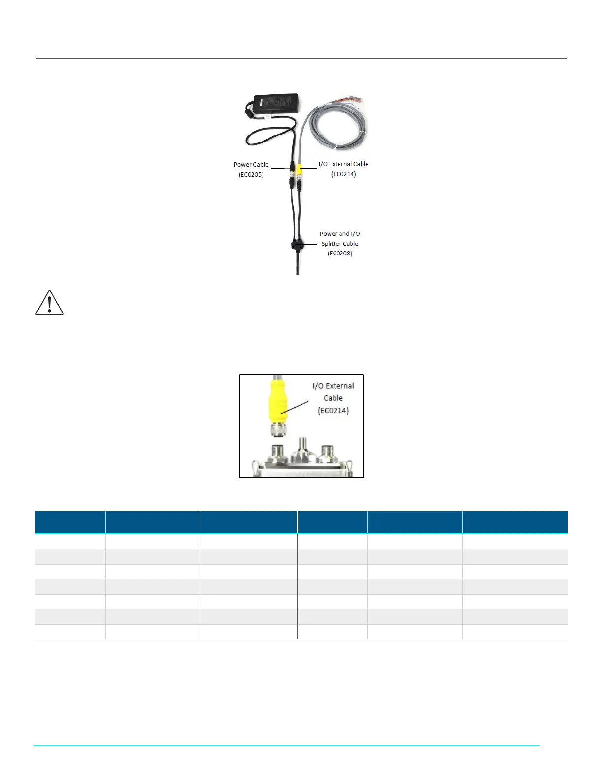
Figure 28. FlowVPX I/O Cable Connections
8. Connect the I/O External Cable (EC0214) to the DAQ device (Figure 29).
Figure 29. I/O External Cable (EC0214) to FlowVPX Head
Table 5. FlowVPX I/O cable (EC0214) pinout
Pin No. Wire Color Function Pin No. Wire Color Function
1 White NC*/+24 VDC 7 Blue Digital Out 0
2 Brown NC*/0 VDC** 8 Red Digital Out 1
3 Green DIO Common 9 Orange Digital Out 2
4 Yellow Digital In 0 10 Tan Analog Ground
5 Gray Digital In 1 11 Black Analog Out 1
6 Pink Digital In 2 12 Violet Analog Out 2
- Bare Ground
*With Power Supply (EC0205) and Power/IO Splitter (EC0208).
**User provided power (24 VDC, 120 W), direct connection to the FlowVPX Head.
Note: If providing a 24 VDC power source, connect the I/O External Cable (EC0214) directly to the Power and I/O labeled connector on
the top of the FlowVPX Head.
WARNING: Explosion hazard for hazardous locations. Do not connect or disconnect any cabling while energized.