21
eRev. 1.08/15/2023
6. Introduction to FlowVPX System Installation
For proper FlowVPX System installation, please be sure to take the following precautions.
• Secure mounting
o Use the standard mount provided with shipment, or
o Use the M6 mounting holes on the FlowVPX Head.
• Minimize system vibrations affecting the FlowVPX instrument to ensure accurate readings.
• Maintain clearance for optical Delivery Fiber or Beams Source and for user interaction with the instrument.
• Safe electrical connections
o Ensure connections are securely attached to the appropriate port or outlet.
o Use no more than one Extender Cable in series if necessary.
• Unstrained cable connections
o Keep a short distance between the light source, computer, and power outlets.
7. Connecting the FlowVPX Head to the FlowVPX Standard Mount
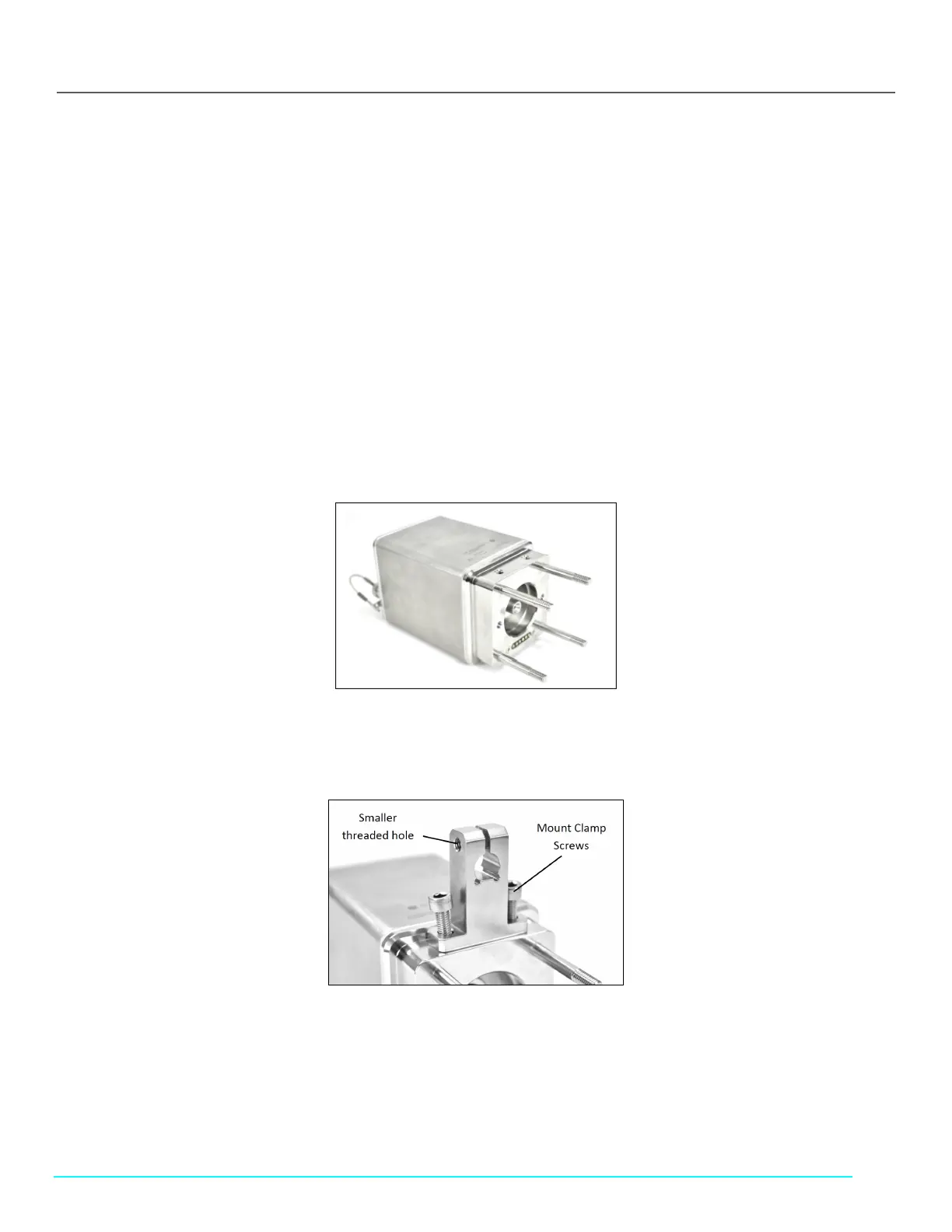
1. Turn the FlowVPX Head on its face (logo side down) so that the two mounting holes are facing up (see Figure 14).
Figure 14. FlowVPX Head (Logo Side Down)
2. Place the Standard Mount Clamp on the FlowVPX Head and align the holes. Ensure that the smaller threaded hole is facing
left (Figure 15).
Figure 15. Standard Mount Clamp on FlowVPX Head
3. Insert the mount clamp screws. Tighten with the provided 5 mm ball end driver (Figure 16).
Figure 16. 5 mm Ball End Driver