33
eRev. 1.08/15/2023
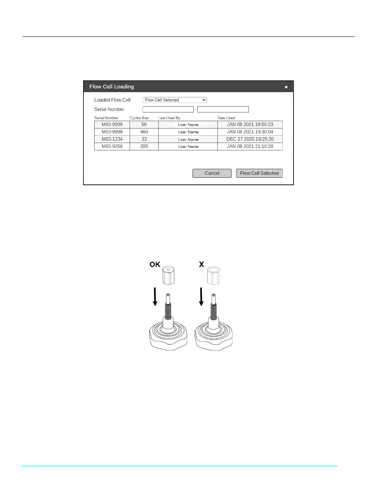
• If previously used, after setting the Loaded Flow Cell dropdown menu to Flow Cell Selected, you may select a Flow
Cell serial number from the table displayed.
Figure 41. Flow Cell Loading Window: Enter Serial Number
9. Click Flow Cell Selected.
10. Click Next Step.
11. Return the FlowVPX to the upright position and ensure the Mounting Post Clamp Handle is tightened.
12. Place and tighten the FX connector nut onto the threaded end of the Fibrette Optical Component, tightening with the
larger-diameter hole facing down (see Figure 42).
• Tighten to 12 in-lbs with the provided torque wrench.
Figure 42. Correct FX Connector Nut Orientation
13. Place and securely hand-tighten the FC connector nut above the FX connector nut.
14. Once it’s tightened, click Locate Zero.
15. Wait for the ViPER software to find the Zero Position.
16. Click Next Step.
17. Place the FC end of the Delivery Fiber on the FC connector nut.
• Line up the key with the keyway, and turn clockwise to secure.
18. Connect the right-angle plug of the Detector Cable (EC0196) to the Detector.
• Ensure the Detector Cable cord is extended upward from the Detector.
19. Click Step Completed.
20. Wait for the Flow Cell Loading Transmission Test Results to appear on the screen.
21. Click OK.