44
eRev. 1.08/15/2023
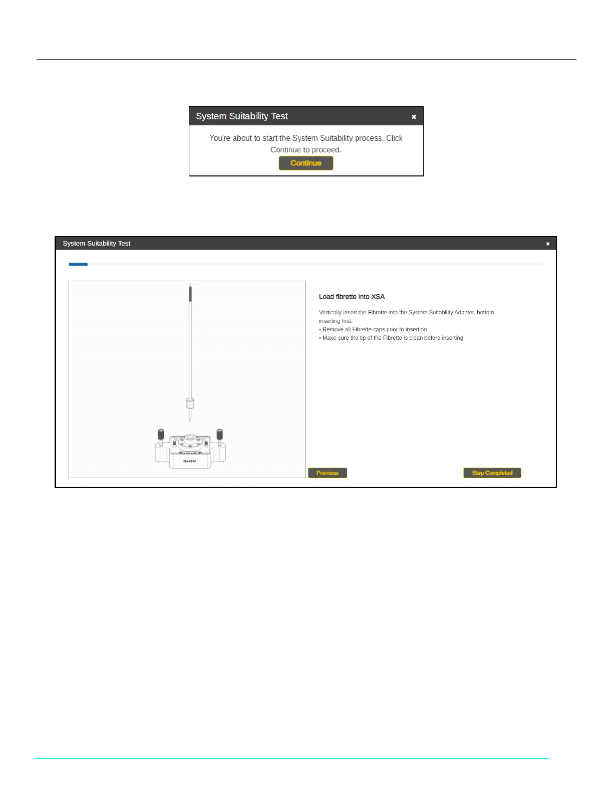
Figure 56. Start System Suitability Test Window
6. Click Continue and follow the on-screen prompts. Click Step Completed to proceed.
Figure 57. System Suitability Test Instructions (Cary 60)
7. Remove all Fibrette caps. Then, load the Fibrette Optical Component into the FlowVPX System Suitability Adapter (XSA).
• Make sure the tip of the Fibrette Optical Component is clean before inserting.
• Insert the tip into the XSA Fibrette Holder first, with the threaded end facing up.
Note: Only use the XSA Fibrette; do not attempt to detach a Fibrette Optical Component that is already connected
to a Flow Cell.
8. Attach Fibrette and XSA unit to the FlowVPX Head.
• Insert the assembled Fibrette and XSA unit into the FlowVPX Head as shown on screen.
• Ensure that the electrical components on the top of the XSA unit and the bottom of the FlowVPX Head line up with
each other.
9. Tighten the VPX Attachment screws on the XSA unit.
• Using a 4 mm hex driver, tighten the screws on the System Suitability Adapter to the FlowVPX Head.
10. Wait for ViPER software to detect the Flow Cell.
• If not detected, the software will guide you to repeat the previous steps.
11. Affix the FX connector nut by aligning and tightening on the threaded end of the Fibrette, with the larger-diameter hole
facing down (see Figure 42).
• Use the 12 in-lbs torque wrench to ensure the nut is fully tightened. Tighten with the torque wrench until there is
an audible click.